News, Updates and Other Minutiae
September 2023 Long time between drinks, but not much happening on the tech front at the moment. Added another couple of rants to the rant page.
January 2023 Updated the AD9833 VFO code to use a 12F1840.
December 2022 Added rant about todays useless (internet) search engines.
November 2022 NEW Project An AD9833 Based Simple VFO. FT101ZD VFO project updated.
October 2022 A replacement internal DDS VFO for FT101Z/ZD rigs. Because the worlds postage system has gone totally bonkers and it is not possible to send a small pcb anywhere except at extreme cost, I am slowly making available the option to purchase pcb's from Pcbway. First up is the Simple DDS VFO 2017 project pcb. Others will be added over time. Noise Canceller kits available again- see Noise Canceller page.
Privacy Policy uploaded. GPDR and all that stuff In accordance with various bits of legislation around the world, either currently in force, about to come into force or proposed, you will now find that annoying "We use cookies" notice at the top of this website. The full Privacy Policy is available at the Privacy Policy link in the footer at the bottom of the page. (If you don't know what GPDR is, Google it. Real scary shit for ANYBODY with a web presence.)
Simple SDR
I was given a Comet SB15 6/2/70 mobile whip and various pre-cut pieces of aluminium for a 3 element yagi (see antenna page), in exchange for building the following project for a friend. The project is a Simple SDR (software defined radio), which was published in the WIA's magazine "Amateur Radio", volume 79, issues 9 & 10 2011. Titled "The Simple SDR: a basic software defined radio anyone can build" by Peter Parker VK3YE. The editor of AR and Peter VK3YE have kindly given me permission to publish the original circuit diagrams from pages 28 and 30 of the October 2011 issue, shown as figure 2 & 3 below. Also see Peter's Youtube video of the original in action. (Links at the bottom of the page). In the schematics, you will notice that they are xtal controlled and cover part of the 40m & 80m bands. My friend would like to have the Simple SDR cover only not the 40m & 80m bands but also the 20m band in full. To accomplish this, a VFO will be required instead of the xtal oscillator. As the build progresses, I will add more information here, but to start, here are the schematics and also some pictures of a donor radio and parts from it.
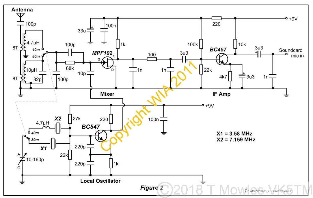
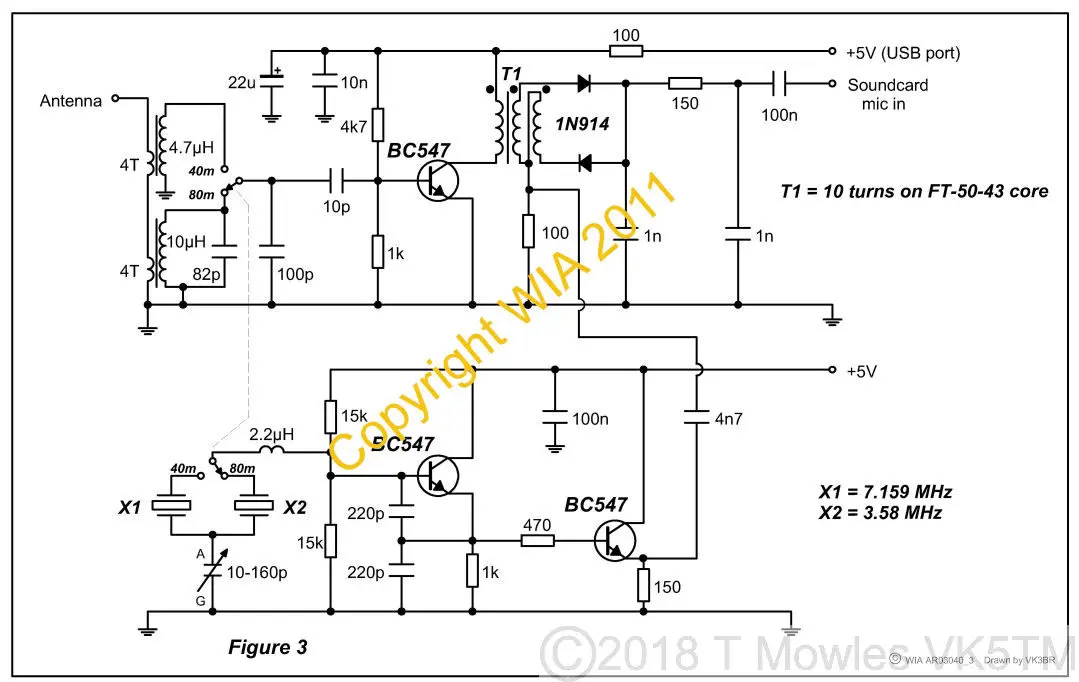
Notice the different output stage and USB powering of the second schematic. (Click images for larger versions. Click again to close.)
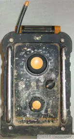
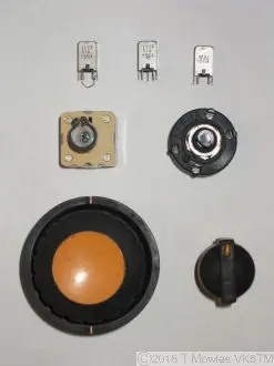
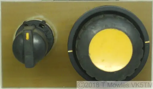
The donor radio is one of those supposedly heavy duty, waterproof radios you find on construction sites. I can tell you they are not that waterproof and this one gave up the if transformers, variable cap, rotary switch, a slow motion drive and a knob for the switch. The coils have been modifed to the inductances needed for the VFO to cover 20m, 40m & 80m. No photo's of the modification unfortunately, as, inside those cans, the formers are about as big as a medium sized ant.
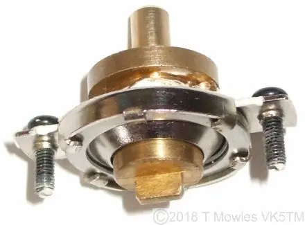
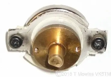
Surprisingly, the slo motion drive, above, does a reasonable job. The white goop around the shaft is supposed to be waterproofing - it doesnt work. Dirt and grit also gets inside the mechanism and needs to be cleaned out. If you can't do it by soaking it in something, you will have to bend those tags up to dismantle it. Be careful, they aren't designed to be bent backwards and forwards that much and may break off.
VFO
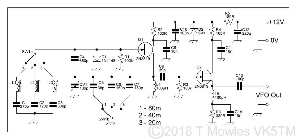
I have done some work on the VFO for the Simple SDR. Below is the schematic that I started with and some photo's showing where it is up to. At this stage, the VFO works on 80m and 40m but is being a bit cantankerous on 20m (I have made some changes to the circuit, so it is a bit different to the drawing).
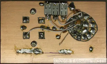
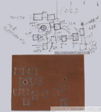
Being a one off, I have not made a pcb for this project, instead marking the islands with a texta and engraving it with a Dremel. Quick and simple.
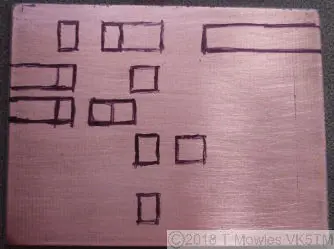
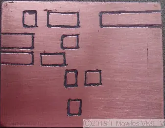
As you can see, not engraved too straight, but it will be hidden in a box so nobody will see it.
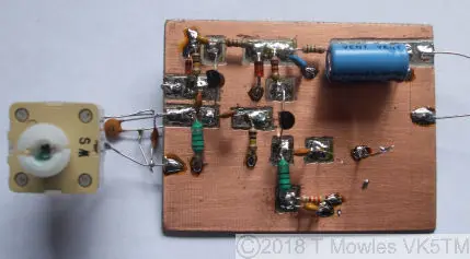
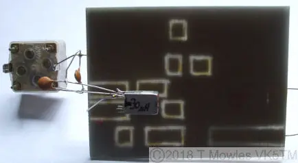
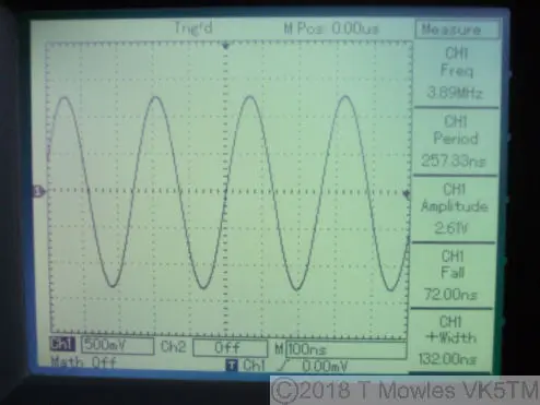
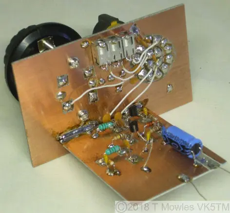
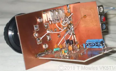
Front and back of the assembled pcb. This is a temporary set-up I used to test the operation of the circuit. As you can see in the scope shot below, a nice clean sine wave with plenty of level (2.6V).
VFO Part 2
OK, got most of the problems sorted in the VFO. It now gives a nice clean sine wave on the 80m,40m 20m bands, although still need to put it on the spectrum analyser to make sure it has no nasty spurs. The output does drop off by about 1V on the 20m band, so we will have to see if that is going to be a problem later. It must be something to do with the frequency response of the 2N3819, although they are supposed to be good into VHF.(These are Fairchild branded ones). The revised schematic is below. For those of a more mathematical design bent, you will notice that the values of C4,C5,C6 and C7 don't match the theoretical values for a Colpitts oscillator of the various frequency bands. I haven't done any investigation as to why, (my guess would be the gate capacitance of the J-Fet) but these values work , so it will stay that way for now.
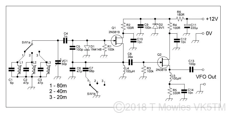
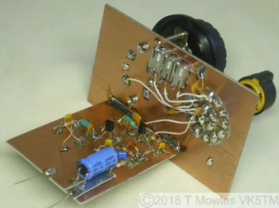
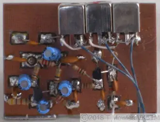
For anybody that may decide to build this VFO, the value of C1,C2 & C3 is chosen to give the band coverage you need and they will vary depending on the coils you are using. In this VFO, I didn't count turns but used an LC meter to give coils of approximately 30uh, 7uh and 1.5uh for the 80m,40m and 20m bands respectively. Depending on the J-Fet you use, C4, C5, C6 and C7 may need adjusting in value as well. There are particular equations for calculating the various capacitor values of a Colpitts oscillator (which you can search the internet for if you really want them) but the following values are those that should have been used here:- 80m - C4 500pf, C5 & C6 1000pf. 40m - C4 210pf, C5 & C6 500pf. 20m - C4 100pf, C5 & C6 250pf.(C7 in this VFO is to increase feedback on the 80m band for reliable starting). Next up is to build the rest of the receiver and try it out, but in the mean time, below are some pictures of the VFO in it's almost finished state, before it goes into a sheilded box.
Receiver
The receiver pcb was made in the same way as the VFO pcb. Mark out the islands with a fine marker and use the Dremel to cut away the copper around them.
To keep the receiver compact, the receive pcb was kept small. As you can see in the photo below, some of the islands probably should have been made a bit larger.
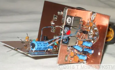
Below are a couple of photo's of the receive pcb mounted to the vfo. When these photo's were taken, I hadn't connected the 40m and 20m coils to the bandswitch (the two loose wires in the photo's), as I wanted to test the receiver on 80m before going too far. Up crops problem #1 - no antenna to connect to it, so, use a signal generator I think. Problem #2 - I don't have a signal generator that goes below 10MHz to test with. The cure was to purchase a couple of the DDS modules available from China, an AD9850 module and an AD9851 module. Having done that and made up a signal generator with one of them (I will describe it on another page), the final wiring was done and the SDR was adjusted. The only thing left to do now , is put up an antenna, hook the SDR to a PC and see what happens. Nearly finished.
Reference & Links Peter VK3YE's video of the original Simple SDR The Wireless Institute of Australia Australia's national ham radio organisation.
