News, Updates and Other Minutiae
March 2025 In something of a "Seniors Moment", I forgot to update the homebrew menu and this section relating to a project I did late 2024. That project is an update of one from the RSGB Radcom magazine of Sept 1999 - 'Turn Your Dip Meter into a Signal Generator'. Presented here as 'Grid Dip Meter (GDO) Add on' under the Homebrew menu.
November 2024 Phillipe F6ETI has done some serious testing on the Noise Canceller and shown it works up to 72MHz and is usable with some loss at 145MHz. Links to his website with photo's, video's and description of the testing on the Noise Canceller page.
September 2023 Long time between drinks, but not much happening on the tech front at the moment. Added another couple of rants to the rant page.
January 2023 Updated the AD9833 VFO code to use a 12F1840.
December 2022 Added rant about todays useless (internet) search engines.
November 2022 NEW Project An AD9833 Based Simple VFO. FT101ZD VFO project updated.
October 2022 A replacement internal DDS VFO for FT101Z/ZD rigs. Because the worlds postage system has gone totally bonkers and it is not possible to send a small pcb anywhere except at extreme cost, I am slowly making available the option to purchase pcb's from Pcbway. First up is the Simple DDS VFO 2017 project pcb. Others will be added over time. Noise Canceller kits available again- see Noise Canceller page.
Privacy Policy uploaded. GPDR and all that stuff In accordance with various bits of legislation around the world, either currently in force, about to come into force or proposed, you will now find that annoying "We use cookies" notice at the top of this website. The full Privacy Policy is available at the Privacy Policy link in the footer at the bottom of the page. (If you don't know what GPDR is, Google it. Real scary shit for ANYBODY with a web presence.)
The Simple DDS VFO - 2017 project pcb can be used for this project. See the Simple DDS VFO page to order.
DDS Xtal Substitute - Updated 2017
This project is an update of both the original DDS Xtal Sub and the Mark 2 version. With xtals getting harder to find 'off the shelf' and the price of custom xtals becoming prohibitive, this project should provide an economical alternative for many applications. The circuit is basically the same as the original Xtal Sub projects, but now uses two push buttons to step up or down through the various programmed frequencies. As the third switch is not needed, it has been dedicated to the calibrate function, which can now be done at any time without needing to reprogram the PIC. Note that the CAL switch is now on a different input from the previous project.
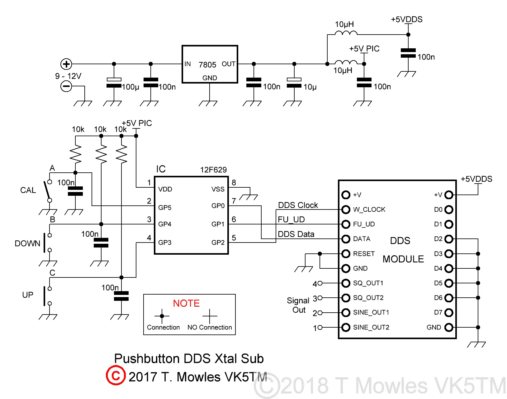
If you have one of the 3.3v modules, all that needs to be done is to replace the 7805 with a 3.3v regulator. The PIC will happily run at 3.3v and it doesn't control anything but the DDS module, so no other interfacing problems.
The UP and DOWN buttons are momentary push buttons that control the selection of the generated frequency while the Calibrate (CAL) switch is either an on/off toggle type or pcb pins and jumper (see calibration paragraph below on its use). Frequency selection, as mentioned, is via the UP/Down buttons, with each selection selected upon release of the button. Selection does not wrap around but stops once the maximum or minimum step has been reached. In the sample software provided below, 8 sets of frequencies are available from 1MHz to 8MHz, but with the code space of the PIC less than half used, many more could be added (or reduced if you need less). As before, these frequencies are of no particular relevance other than a means of testing. The pcb is only 2 inches (50.8mm) square. You can use either the AD9850 Module or the same format AD9851 module. Extra pads have been added for the square wave outputs.
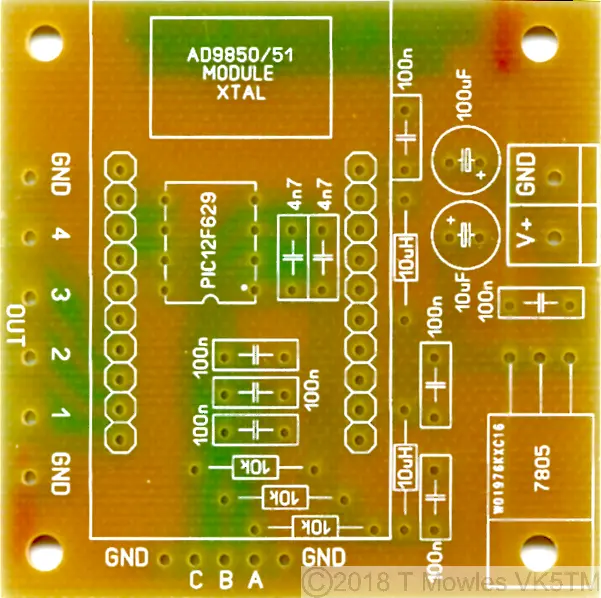
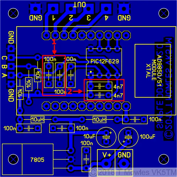
A word about the two sets of capacitors marked 1 and 2 - for this project, only fit the capacitors in the red box marked 1. Just for clarification, the 100n capacitor next to, but not with-in the red box marked 1, must be fitted.
Software
There have been a few cases of errors compiling files and it is caused by using an older version of MPlab. I use version 8.92 (which is the last of the old MPlab versions) and the problem relates to the 'include' file and the Config defines of those older versions. Specifically the FOSC_INTRCIO definition of the later version - change it to INTRC_OSC_NOCLKOUT for earlier versions of MPlab.A few words about the software. The PIC goes to sleep once a frequency has been selected and wakes again when either the UP or DOWN button is pushed. Also, at power on, the generated frequency is the first one in the list, the software does not remember the last used frequency as there is currently no external indication of which step it was (I have a half formed idea on using the CAL input to provide some sort of indication of the currently selected step). You will need to input the values of and recompile the software for your required set of frequencies: Xtal_1_0...3 to Xtal_8_0...3 in the asm file are the frequencies that the DDS will be set to. The number of indiviual frequencies can be decreased or increased (up to the maximum code space available in the PIC) to suit your requirements. The Calibration frequency - This is the frequency the unit needs to be adjusted to during the calibration procedure. I suggest making it in the middle of your range of frequencies. How to calculate these is presented further down this page. There is no limit to the frequency range other than that of the AD9850 or AD9851. If you use MPlab to compile the software, the above are between lines 137 to 196 in the asm file.
Calculating and entering different frequencies
For those with Windows systems, it is easier to use the upgraded scientific calculator available for download (in "Programmer" mode) or you can use the HEX Calculator described below. Users of other operating system (or those that don't want to download the calculator), will need a decimal to hex converter program of some sort (unless you are lucky enough to be able to do it in your head). In the asm file, starting from line 137, are several 'EQU' statements for xtal_1_0..3, xtal_2_0..3, xtal_3_0..3, through to xtal_8_0..3 and the calibrate frequency. I will use the value of 5MHz to show you how to get the numbers. The following sequence applies to all of the 'EQU' sections (with different numbers of course). Firstly, enter the dec number 5000000 (5 million) into your dec to hex calculator/program (I'm not going to tell you how to work your calculator/program, you need to work that out yourself). The HEX number will be 4C4B40 Now break this number down into groups of 2, starting from the right hand side:- 4C 4B 40 The right hand number is the least significant byte, so you enter 0x40 into the line that says, funnily enough, least significant byte. Enter 0x4B in the next line up and 0x4C into the line above that. The '0x' tells the MPlab compiler that the number is in HEX format. So, where is the most significant byte? Well, in this case, it is 00, because 5000000 only converts to the three bytes just shown. So, if your calculation only gives you three nice even groups of two numbers, the most significant byte will be 0x00. Lets do another one that doesn't give you three nice even groups of two numbers. Enter 20000000 (twenty million) into your calculator/program. It should come back with the HEX number of 1312D00. Breaking that down into groups of 2 as before gives you: 1 31 2D 00. Not so nice even groups of two numbers plus an odd one. To fix that, you put a '0' in front of the 1 to get 01 31 2D 00. Because nought is nought (or zero is zero), it has no effect on the calculated value, so you can enter the numbers as before, but the most significant byte will now be 01. Don't forget to put 0x in front of your numbers, otherwise, strange things will happen. Using the AD9850 or '51 modules, the most significant byte will not be any more than 03 hex (which puts you upwards of 50MHz). Increasing or reducing the number of frequencies available will require adding or removing some blocks of code as follows. First, reducing the number of frequencies. The EQU statements starting at line 137 contain the frequencies, so, for example to reduce the number to 4 frequencies, everything between line 163 and line 190 can either be removed or commented out. Next, at line 393 is the code 'xorlw 9'. Change that to 'xorlw 5'. This number is ALWAYS 1 bigger than the number of frequencies available. At line 396 is the code 'movlw 8'. Change that to 'movlw 4'. This number is equal to the number of frequencies available. Now the code between lines 416 and 431 can be removed or commented out. Lastly the code between lines 495 and 553 can likewise be removed or commented out. Now, increasing the number of frequencies. I will show you the example of adding 1 more frequency for a total of 9 frequencies. You will need to add an extra EQU block after line 190 like so (changing the values to your calculated values):- xtal_9_3 equ 0x00 ; Most significant byte for 8.000 MHz xtal_9_2 equ 0x7A ; Next byte xtal_9_1 equ 0x12 ; Next byte xtal_9_0 equ 0x00 ; Least significant byte Because the line numbers will now change, you will need to find the code that was at line 393 and change it to 'xorlw 10' Then find the code that was at line 396 and change it to 'movlw 9'. After the block of code that looks like this:- movfw frequency xorlw 8 ; Test if 'frequency' = 8 btfsc STATUS,Z ; Return to 'main if not 8 goto xtal_8 ; = 8 so set frequency to xtal_8 value Add another block like so:- movfw frequency xorlw 9 ; Test if 'frequency' = 9 btfsc STATUS,Z ; Return to 'main if not 9 goto xtal_9 ; = 9 so set frequency to xtal_9 value Likewise, after the block of code that looks like this:- xtal_8 ; Frequency 8 movlw xtal_8_3 movwf freq_3 movlw xtal_8_2 movwf freq_2 movlw xtal_8_1 movwf freq_1 movlw xtal_8_0 movwf freq_0 call calc_dds_word ; Convert to delta value call send_dds_word ; Send frequency to the AD9850/AD9851 goto main ; Continue main loop Add the same with the references increased to '9' like so:- xtal_9 ; Frequency 9 movlw xtal_9_3 movwf freq_3 movlw xtal_9_2 movwf freq_2 movlw xtal_9_1 movwf freq_1 movlw xtal_9_0 movwf freq_0 call calc_dds_word ; Convert to delta value call send_dds_word ; Send frequency to the AD9850/AD9851 goto main ; Continue main loop After you have recompiled the software, you should now have 9 different frequencies available.
Calibration
Once you have built the unit, it really should be calibrated before you fit it into anything. Calibration requires the use of an accurate frequency counter with 1Hz resolution and is used to adjust the "OSC" values in software to correct for off frequency Xtals on the DDS modules. Note that the calibration routine can only be entered at power up. Connect the frequency counter to the output of the unit and turn the switch connected to input 3 ON (or jumper the pcb pins). Do not turn it off or remove the jumper until calibration is complete. Apply power. The frequency counter should show a frequency somewhere in the vicinity of the calibration value put into the software. Go away and have a cup of coffee, maybe a biscuit or 2 or what ever your choice. Once you have left the unit to run for a minimum of fifteen minutes, then continue. Or in other words, give it time to warm up before doing any adjustments. Push and hold either the UP or DOWN button as is required to change the frequency so that it becomes your calibration value. There is approximately a 200mS delay between each frequency change step. Because the frequency steps used in the calibration routine are very small, it may take a few moments before you see any changes in the displayed frequency. Release the button when you have reached the CAL frequency. You can now turn the CAL switch OFF or remove the jumper. This will save the new computed "OSC" values into EEPROM and the unit will now be functional. If you find that you have not quite correctly set the calibration, you can follow the steps above again to perform another calibration (there is no need to reprogram the PIC as was required by previous versions). At this point, you can remove power and fit it into what ever it is you are going to use it in.
Hex Calculator
Alan, G8UJS, has kindly supplied an Excel spreadsheet (in the Downloads section below) which can be used to calculate the Hex values for different xtal substitute frequencies. No more fumbling or head scratching with that rotten calculator. A point to note is that this file will only work in the newer versions of Excel. It will also calculate the values for different frequency oscillators on the AD9850/51 modules. To use, open the Excel file and click on the Yellow area to enter your frequency (double click to enter directly in the box or enter your numbers in the area above the column designators). It may ask you to "Enable Editing", go ahead and click yes (otherwise it won't work). Then either hit "Enter" or click out of the box and your answer will magically appear in the box next to the one you changed. You still need to seperate out the Hex number into it's individual pairs and add the 0x. Most people can ignore the section on the right unless you are converting old Pye units to 4m, when this may come in handy. If you want to keep the numbers when closing Excel, click yes to save, otherwise click no to keep the file as is (I recommend keeping a copy of the Excel file somewhere else in case you make an error and corrupt the file).
Downloads
These files are provided free for personal use ONLY. I retain copyright on all works published on this website (unless otherwise specified). These files, or any derivative of them, may NOT be used in any commercial or profit making enterprise of any kind. I no longer make the pcb files available because of copyright infringement.
(Right click and 'Save as..' or what ever is required by your browser) VK5TM_DDS_XTAL_SUB_2017.asm The ASM file for the Xtal substitute project. It is set to AD9850 by default. Instructions are in the file to change it. VK5TM_DDS_XTAL_SUB_2017.HEX The HEX file is for the AD9850 and has the 8 frequencies as described above. DDS_HEX_CALCULATOR.xlsx Kindly supplied by Alan, G8UJS.
