News, Updates and Other Minutiae
March 2025 In something of a "Seniors Moment", I forgot to update the homebrew menu and this section relating to a project I did late 2024. That project is an update of one from the RSGB Radcom magazine of Sept 1999 - 'Turn Your Dip Meter into a Signal Generator'. Presented here as 'Grid Dip Meter (GDO) Add on' under the Homebrew menu.
November 2024 Phillipe F6ETI has done some serious testing on the Noise Canceller and shown it works up to 72MHz and is usable with some loss at 145MHz. Links to his website with photo's, video's and description of the testing on the Noise Canceller page.
September 2023 Long time between drinks, but not much happening on the tech front at the moment. Added another couple of rants to the rant page.
January 2023 Updated the AD9833 VFO code to use a 12F1840.
December 2022 Added rant about todays useless (internet) search engines.
November 2022 NEW Project An AD9833 Based Simple VFO. FT101ZD VFO project updated.
October 2022 A replacement internal DDS VFO for FT101Z/ZD rigs. Because the worlds postage system has gone totally bonkers and it is not possible to send a small pcb anywhere except at extreme cost, I am slowly making available the option to purchase pcb's from Pcbway. First up is the Simple DDS VFO 2017 project pcb. Others will be added over time. Noise Canceller kits available again- see Noise Canceller page.
Privacy Policy uploaded. GPDR and all that stuff In accordance with various bits of legislation around the world, either currently in force, about to come into force or proposed, you will now find that annoying "We use cookies" notice at the top of this website. The full Privacy Policy is available at the Privacy Policy link in the footer at the bottom of the page. (If you don't know what GPDR is, Google it. Real scary shit for ANYBODY with a web presence.)
Pic-a-Star Si5351 Local Oscillator Module
This project is not restricted to use in a Pic-a-Star, it can be used (almost) anywhere a substitute for a xtal is needed. This project came about after a discussion between myself and Glenn VK3PE, a well known Pic-a-Star builder, Glenn's website. As many are aware, quartz crystals in custom frequencies (and even some that used to be standard frequencies) are now getting very expensive, so an alternative was sought. This module has been designed to generate either 10.710MHz or 10.715MHz, (to suit the commonly used, 10.695 or 10.70MHz crystal filters) but those with the requisite skills can change that to suit other filters or applications. An explanation of the steps involved can be found here Si5351 Local Oscillator Module Pt2 - Modifying the Si5351 Local Oscillator Module frequency output. Although specifically conceived to fill a need in the Pic-a-Star rigs, this module can be used in other projects. See the other page linked above.
Build information
This project should be an easy build for those experienced in using SMD components. Having said that, those of you with average to good soldering skills and a steady hand should also be able to do it with a little patience and perserverance.
This build description is only a suggestion of how to go about it but there are several important points to note that will be explained through the procedure. The following numbered drawing corresponds to the numbered steps below. Please read completely through them first before commencing construction. Schematic, software, BOM and other information is available to download at the bottom of this page.
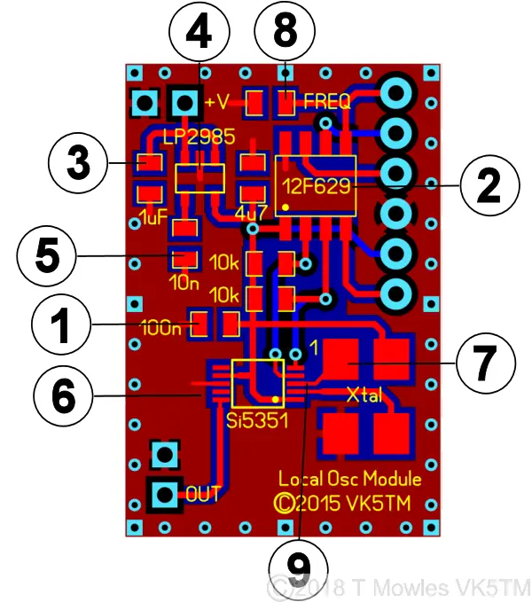
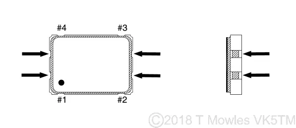
1:- FIRST IMPORTANT NOTE: The PIC is static sensitve, so safe anti-static work practices should be used. A programmed PIC can be erased or otherwise be made non-operative from the effects of static electricity (ask me how I know this!). Install the 100n capacitor FIRST, regardless of whether you are going to program the PIC once installed on the pcb, have already programmed the PIC or have purchased a programmed PIC. 2:- Install the PIC. If programming on board, do it now. The header pins on the right hand side are set-up to work with a PicKit 2 or 3 programmer (see component overlay diagram further down). For other programmers, you will need to make up an approriate cable. See important note about programming at the bottom of the page. 3:- Install the 1uF and 4.7uF capacitors. These are Multi Layer Ceramic Caps (MLCC) and are not polarity sensitive. SECOND IMPORTANT NOTE: DO NOT use Electrolytic or Tantalum caps, they do not have the right characteristics for use in this circuit. 4:- Install the LP2985 3.3v regulator. 5:- Install the 10n cap and 2 x 10k resistors. 6:- This is the part that needs the most care in mounting - the Si5351 - the pins are very close together (read very small!). A good magnifier and plenty of flux are your friends. I soldered this using the "flood soldering method" - i.e. Apply flux, position chip (the right way round) and solder across all the pins on both sides (don't worry about the solder bridges). Next, with more flux and de-soldering braid, remove the excess solder. Although it may appear that all the solder has been removed, there will be more than sufficient under the pins for a good connection to the pads. Don't be tempted to "touch up" the pins with a bit of extra solder, you are only asking for a world of trouble. 7:- Fit the oscillator module (see also point 9). The BOM (bill of materials) lists a 7 x 5mm oscillator module, which is a tight fit on these pad spacings. You may want to source a 5 x 3mm module instead. THIRD IMPORTANT NOTE: (and one that caught me out) - some oscillator modules have small pads on the ends (see drawing below), which for no logical or sensible reason are not connected to their adjacent pins. In the oscillator module I used, that pad adjacent to pin 2, was connected to pin 1! DO NOT get solder on these pads!!!
8:- This is where you decide which frequency to generate. The default frequency is 10.710MHz and if this is the frequency you want, you can skip this step.
An alternative frequency of 10.715MHz can be generated and this is done by placing a zero ohm 0805 resistor or linking the two pads with a piece of wire at the position marked "FREQ". Note that this is an either/or function, you cannot switch between the two frequencies while your rig is powered on.
9:- Some oscillator modules have pin 1 assigned to an enable/disable function and shouldn't be a problem with the pcb layout. However, if your module won't oscillate or is erractic in operation, it may be desirable to cut the trace going to pin 3 of the Si5351. Use a sharp instrument and CAREFULLY cut the trace, making sure not to damage the one going to pin 2. This can be done prior to assembly regardless of the type of oscillator module if desired.
While an oscillator module is the preferred option for driving the Si5351, this pcb has the option of using a 25MHz quartz crystal (not recommended). This can be mounted across pads 1 and 4 in the oscillator module location. However, you may need to add additional capacitors to match the crystal to the load set in software (10pF) and one should be a trimcap to bring the crystal on frequency. These should be mounted between pin 1 and ground and pin 4 and ground.
The above option of using a crystal instead of an oscillator module has been removed for the next run of pcb's, so there will be no need to cut the track.
That is basically the build information, so the next step is check and double check that everything is in the correct place, correctly oriented and soldered and that there are no solder bridges. All that remains is to connect a source of power between 5V and 12V (the regulator is a low dropout type and will work satisfactorily from 5V) and check the output. Fitted to Picastar, the module is best connected to the 10 volt supply rail, via the 100uH choke (RFC610) in the oscillator partition.
Connecting the Module to a rig
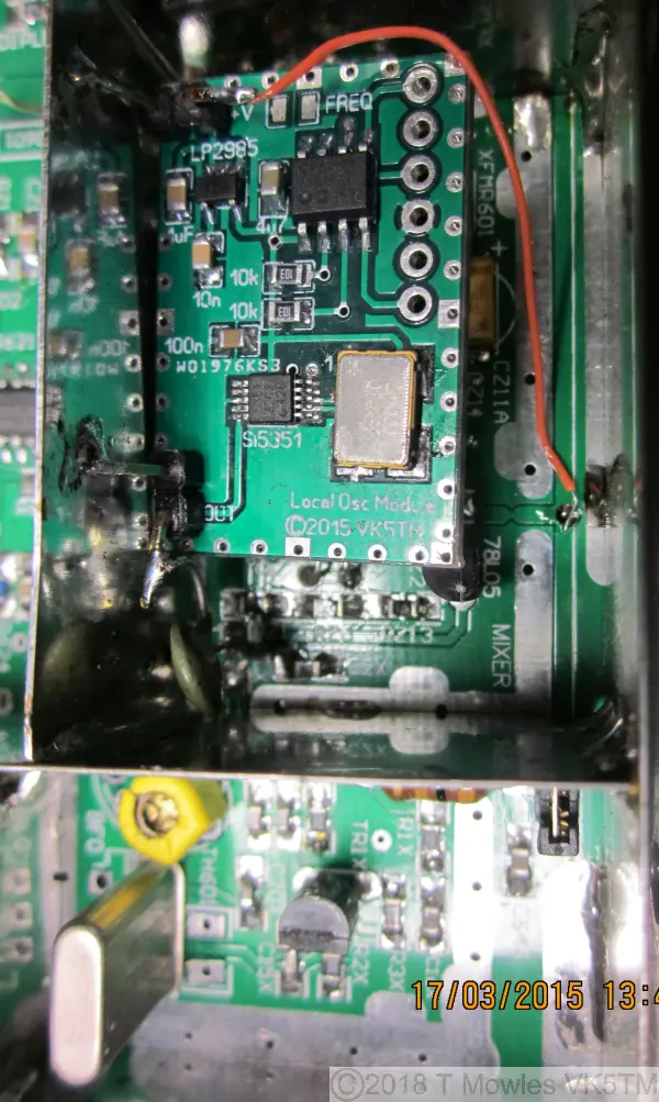
I don't have a Pic-a-Star, so the information below is courtesy of Glenn's (VK3PE) testing of the prototype. The pic below is the module mounted in one of Glenn's already finished 'Star's. The original oscillator has been disabled and the Si5351 module fitted in the Mixer area for testing only. Normally the module will be mounted in the 2nd oscillator partition (bottom of picture). Output from the module is routed via a 33pF cap to the mixer and the output ground pin and supply ground pin has been soldered to the shield. The via's around the edge of the module are all grounded, so you can use these to solder the shield to. That's all there really is to it. Glenn reports no difference in listening test's, but currently doesn't have the equipment necessary to do any proper testing.
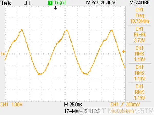
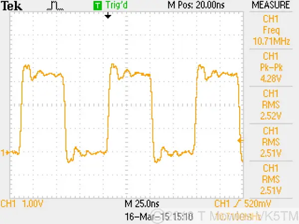
The two scope traces below show, top, the output of the original oscillator circuit and below, the unloaded output of the Si5351 module at 4.28V p - p. The loaded output of the module is about 3.3v p - p.
Downloads and other information
These files are provided free for personal use ONLY. I retain all copyright on all works published on this website, except as otherwise noted. They may NOT be used in any commercial or profit making enterprise of any kind without the express WRITTEN permission of the copyright holder.
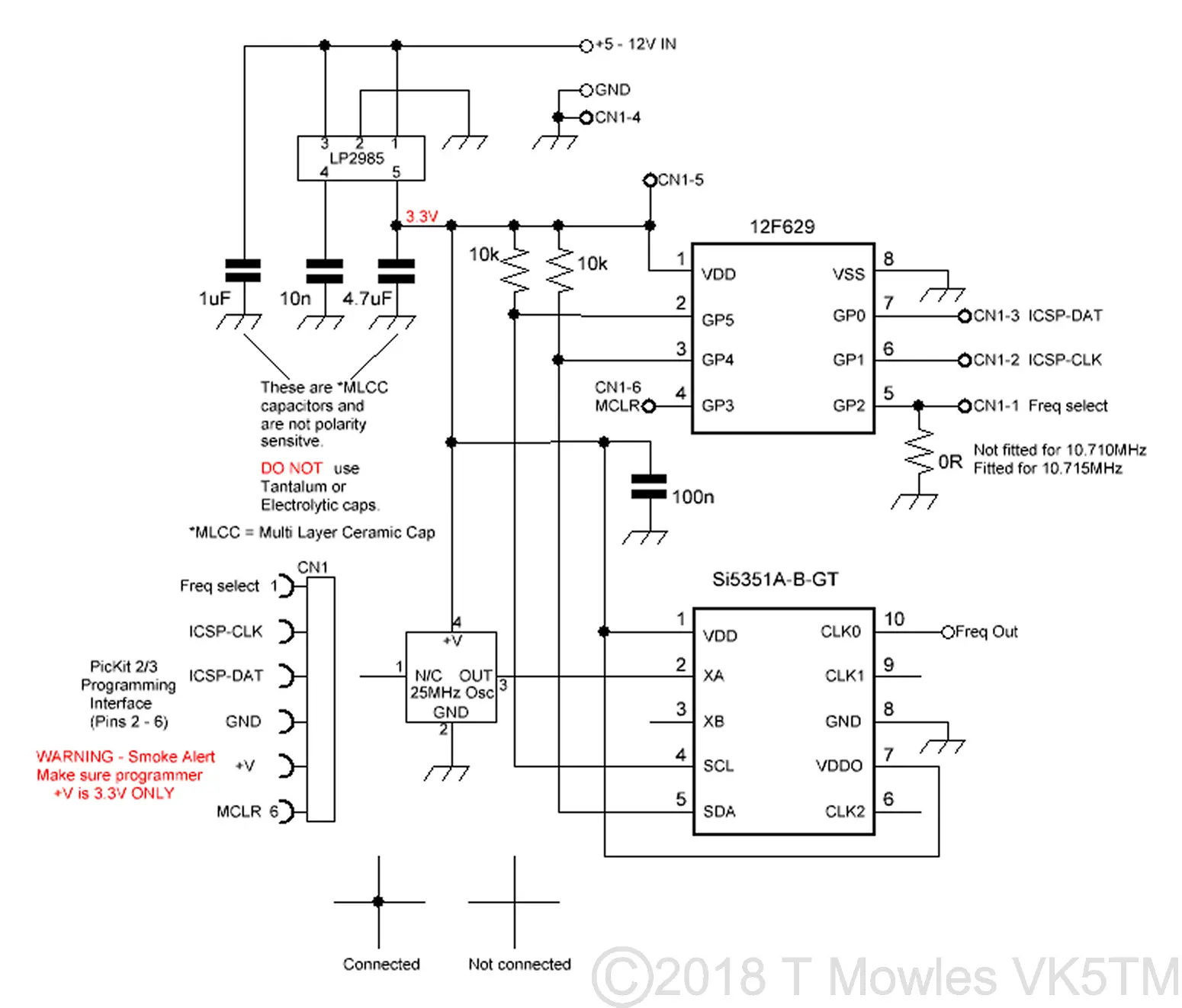
Here is the schematic of the module.(Click picture for larger view. Click again to close.)
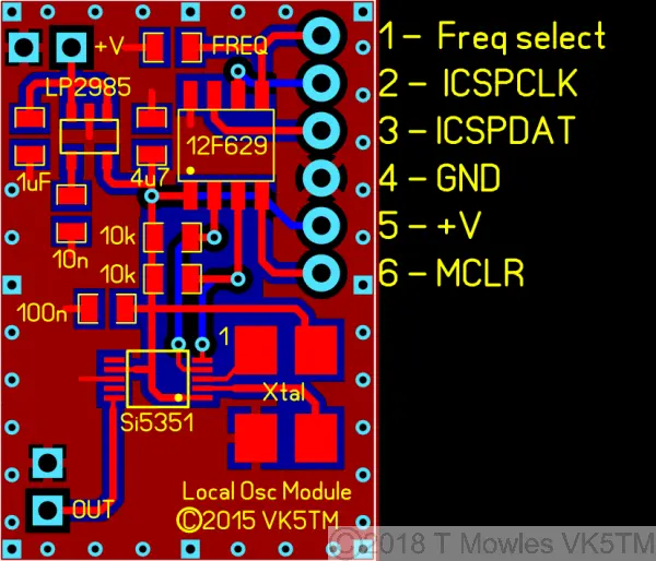
And component overlay and programming connector details.
Downloads: (Right click and 'Save as..' or what ever is required by your browser) A pdf of the 'Star LO/IF schematic for connecting the Si5351. Courtesy Glenn VK3PE. The bill of materials. This lists Mouser part numbers and RS Australia part numbers. You can use any equivalent parts sourced from your favourite component supplier if available. BOM.TXT Software Download: VK5TM_Si5351_LO.asm VK5TM_Si5351_LO.HEX
NOTE -> SMOKE ALERT. If you have a fully loaded module and are experimenting with changing the program (or forgot to program the PIC in a previous step), it is VITAL that your programmer does not output more than 3.3V on it's V+ pin. If it does, you will let out the all important smoke and the module will never work again.
