News, Updates and Other Minutiae
August 2025 UR5WHK has created another version of the AD9833 project with a 128 X 32 OLED display. You can find it under the Gallery menu - it is on the same page as the MAX7219 version.
July 2025 UR5WHK has created an updated version of the AD9833 project which now includes a MAX7219 based LED display. Code updated 10 July 2025. Code updated again 15 July 2025. You can find it under the Gallery menu.
March 2025 In something of a "Seniors Moment", I forgot to update the homebrew menu and this section relating to a project I did late 2024. That project is an update of one from the RSGB Radcom magazine of Sept 1999 - 'Turn Your Dip Meter into a Signal Generator'. Presented here as 'Grid Dip Meter (GDO) Add on' under the Homebrew menu.
November 2024 Phillipe F6ETI has done some serious testing on the Noise Canceller and shown it works up to 72MHz and is usable with some loss at 145MHz. Links to his website with photo's, video's and description of the testing on the Noise Canceller page.
Privacy Policy uploaded. GPDR and all that stuff In accordance with various bits of legislation around the world, either currently in force, about to come into force or proposed, you will now find that annoying "We use cookies" notice at the top of this website. The full Privacy Policy is available at the Privacy Policy link in the footer at the bottom of the page. (If you don't know what GPDR is, Google it. Real scary shit for ANYBODY with a web presence.)
Updated - Lead Acid Battery Voltage Monitor - CQ January 1999
A Simple Lead Acid/SLA battery monitor.
I, like many of us I suspect, have a few SLA/AGM batteries floating around the workshop that I invariably forget to charge occasionally and because the brain gets more forgetful as one gets older (don't I know it), I thought some sort of monitoring system would probably be a smart idea.
Digging around the 'net, I came across Gerry Crenshaw's (WD4BIS) website https://www.qsl.net/wd4bis/ and in among the PIC Projects section was a Battery Monitor project.
Now this project was originally developed by DEREK TOEPPEN, WA0ZTI and published in CQ Magazine, January 1999.
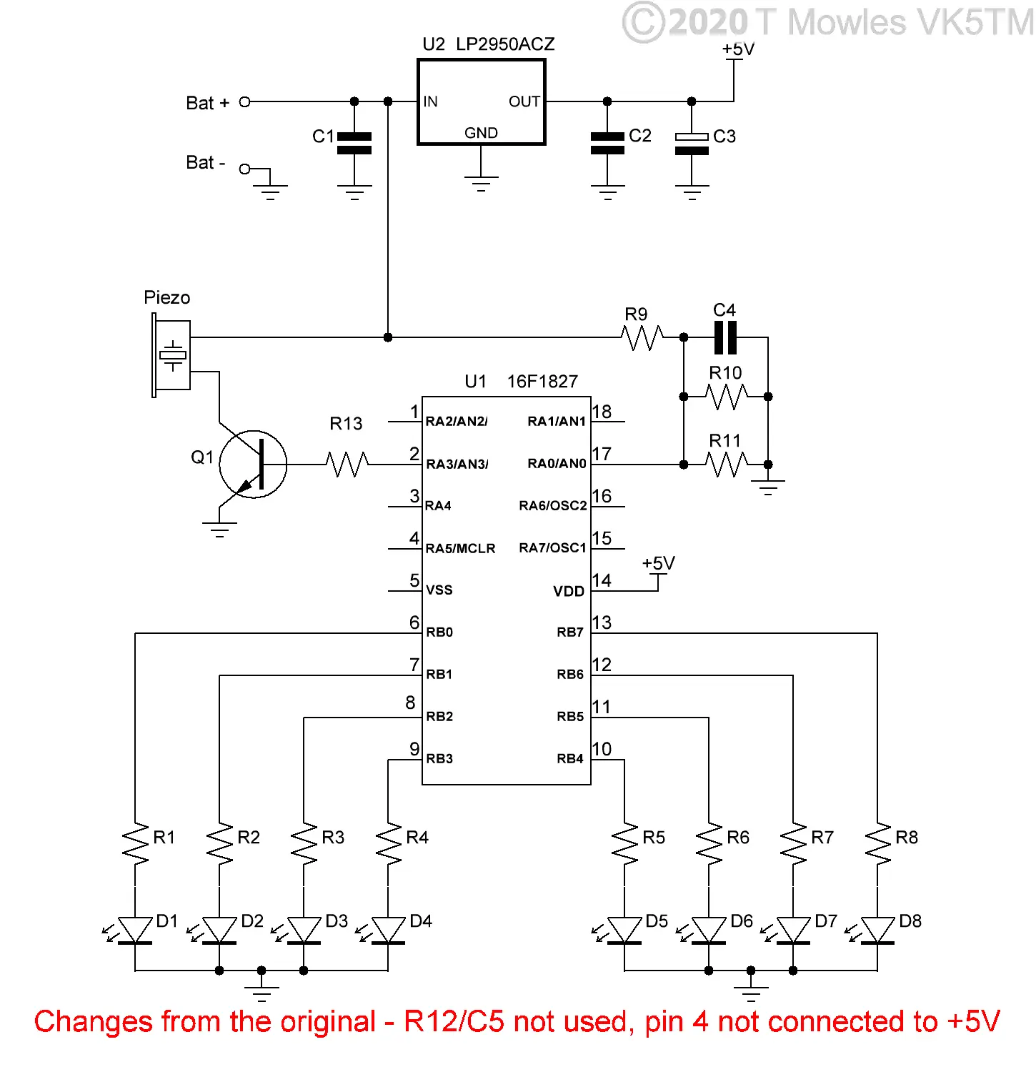
The original premise of this project was to monitor Lead Acid Batteries used in Field Days and originally used a 16C71 PIC microcontroller as the heart of the device. Being as simple as, I figured that this will do the job, but I decided that it would be better to update the PIC to a more modern device, the result being the code available for download below to use in a 16F1827 PIC (a straight plug-in replacement hardware wise).
Basically, all it does is periodically measure the battery voltage and if it has dropped to or below 10.6V, it sounds an alarm.
In a departure from the original code, instead of checking every few seconds, my version checks the battery voltage about every 32 seconds (32 seconds? - yes, it is a function of dividers and timers in the PIC), also the beginning test sequence runs for about 8 seconds instead of the original 40'ish seconds.
Now, before you go "But there's no component values in the schematic!", there is a reason - I don't need to monitor batteries 'out in the field', so I am working on have an even more updated version that can monitor up to 5 batteries at once, for use in a workshop setting. Visit Gerry's website (link above) for information on the original version or dig up a copy of CQ Magazine for January 1999.
Scroll down for my updated version.
Downloads for the original 1999 Battery Monitor project
These files are provided free for personal use ONLY. I retain copyright on all works published on this website (unless otherwise specified). These files, or any derivative of them, may NOT be used in any commercial or profit making enterprise of any kind.
(Right click and 'Save as..' or what ever is required by your browser) batmon_16F1827.asm The ASM file for the original Battery Monitor project. batmon_16F1827.HEX Battery Monitor hex for the original project.
VK5TM Updated Lead Acid Battery Voltage Monitor
OK, before we get into the technical details, you should note that this project is as dumb as...(insert favourite phrase here)..., it can't tell you what colour jocks you're wearing, predict the future or anything else even remotely interesting. It is nothing more than an automated voltage monitoring and alarm unit. You are the smarts! Yes I know all about Lithium this and that batteries with the (in most cases) smarts built in to the battery, but there are still plenty of us fuddy duddies that use 'old fashioned' batteries. Ok, lets get to the capabilities etc. As mentioned above, his unit is nothing more than an automated voltage monitor (specifically for 12V lead acid/SLA/AGM batteries) and can monitor up to 5 batteries at once. If/when any one of them drops to a terminal voltage of 10.6V or less, an alarm sounds and one of the LED's flash to indicate which battery has tripped the alarm. The board will stay this way until it is powered down to reset it. Here is a pic of an assembled prototype, those with a keen eye will note that the zener diodes are not fitted - that's because the power supply I was using to test it doesn't go much above 14V, also, it is a V1.2 pcb, the final pcb is V1.3 and looks exactly the same except for one track alteration on the bottom side.
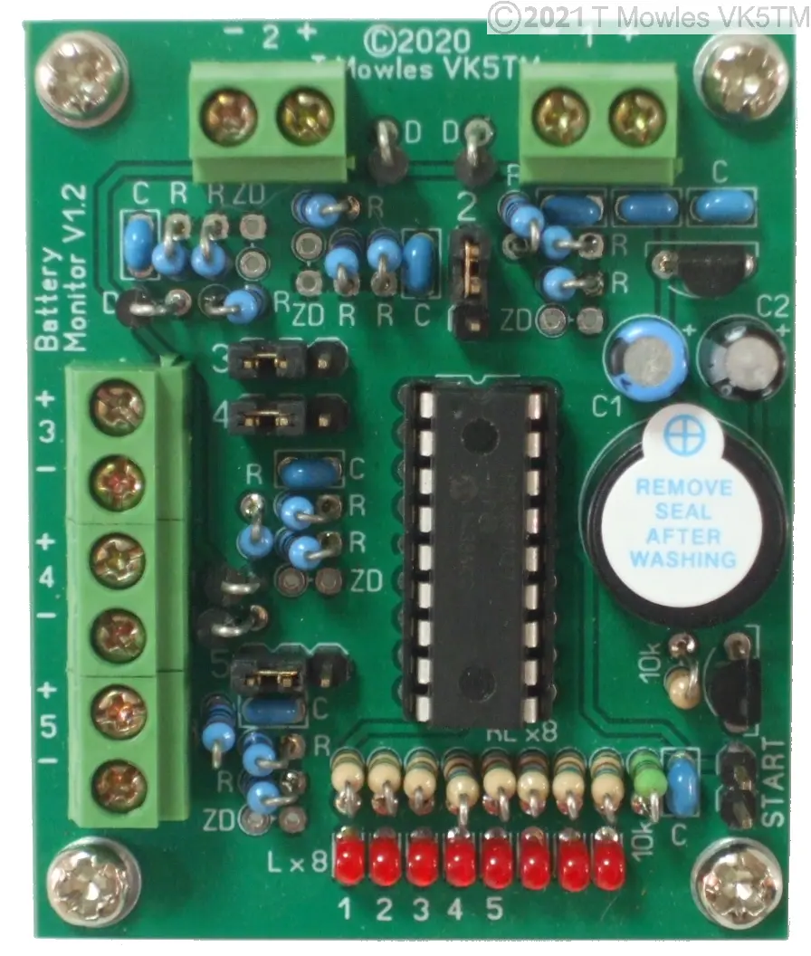
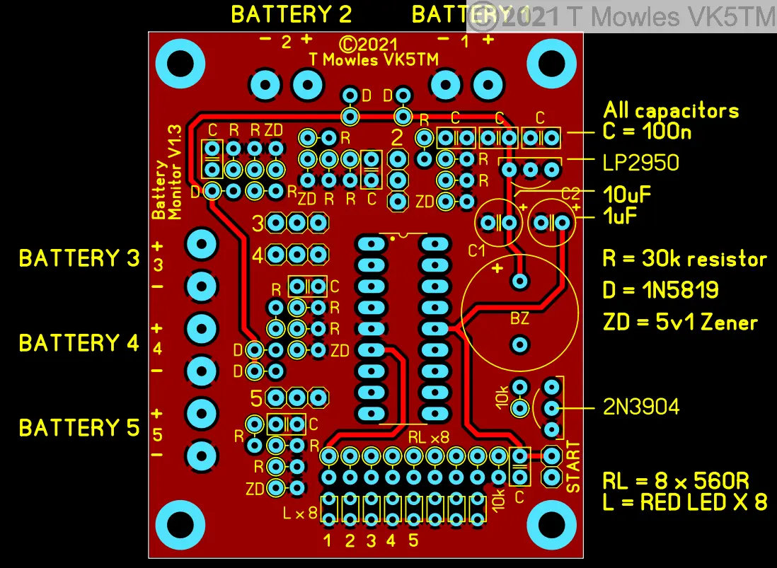
All the components marked 'C' are the same value as are those marked 'R' etc. 'RL' are the LED resistors and although 560R resistors are shown on the schematic, 1k or slightly higher would probably be more appropriate (they will have to be higher still if you use high efficiency LED's). Of note are the LED's, they are rectangular, I used RS part # 861-0043 RED LED - ordinary 3mm round ones won't fit the space unless you do some judicious wire bending. So: R = 30k 1% Metal Film 0.25 or 0.6W resistors. RL = 560 ohm resistor - as these are LED resistors you can use ordinary carbon or metal film 0.25W style. C = 100n 50V monolitihic 0.1" capacitors. C1 = 10uF 25V electrolytic capacitor. C2 = 1uF electrolytic capacitor - low voltage ones seem to be a rarity, so any voltage above 6V is fine. D = 1N5819 Schottky diodes - do not substitute, these have been used for their low forward voltage drop. ZD = 1N751 5.1V 400mW Zener diode. Transistor is a 2N3904 Voltage reg is LP2950-5 - again do not substitute. Buzzer is Piezo with 7.62mm pin spacing - use what you like but note that it is powered from the input voltage, not the 5V rail. There's a couple of 10k resistors and various terminals to finish it off. You can see from the pic above what I used for connectors and header pins, you are free to use what you have as long as it fits the space.
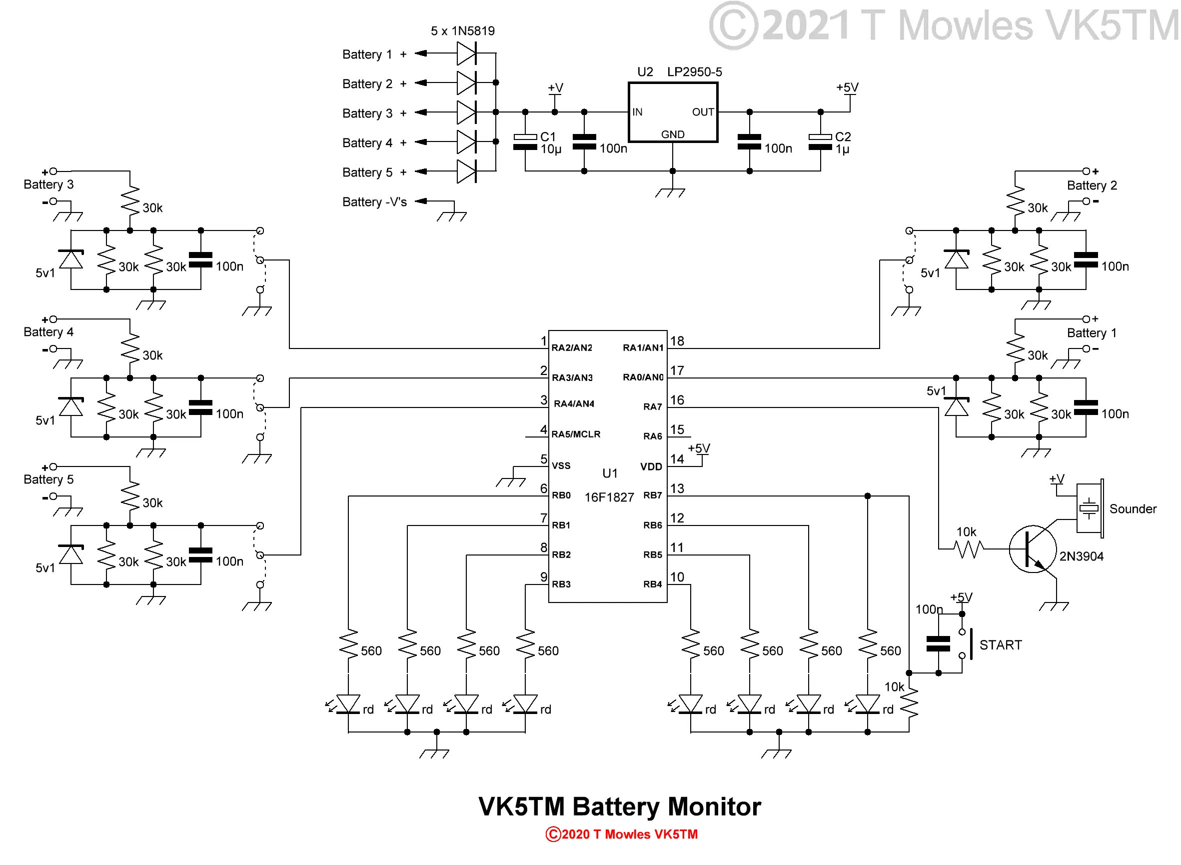
As you can see, there is very little to it, basically a PIC, a power supply, some human interface units (LED's, switch and a piezo buzzer in English) and some external world to digital interconnect hardware (ok, ok, voltage divider and protection circuit for the PIC). The PIC chosen for this is the enhanced mid range 16F1827, maybe not the latest and greatest, but it does have a lot more functions squeezed in to it than we hobbyists have normally been used to, plus a lot more memory and it is cheaper than the 16F88, one of the staples of the hobbyist for years past. Hardware wise, the 16F1827 is a direct drop in for a lot of the older PIC's. Software wise, well, there are a few things to get your head around. This unit is powered by the battery(s) connected to it, anywhere from 1 to a maximum of 5. All the batteries connected can contribute to supplying power, although the one with the highest terminal voltage will contribute the lions share of the current. The diodes shown connected to the voltage regulator input prevent the batteries back feeding one another and upsetting the voltage measuring set-up. The current draw of this unit (in monitor without display mode - see below) is literally only a few micro-amps when actually measuring voltage and nano-amps when in sleep mode so it will have an insignificant affect on the state of charge of any connected batteries. Additionally, the LED's only draw 5mA each for a short period during the other modes and this could be reduced further by increasing the value of the series resistor. Don't be tempted to substitute a 7805/78L05 for the specified 5v regulator, it's quiescent current is too high. What are the little circles with dotted lines between them? Well, they are pin headers so that the little bit of smarts programmed in can determine how many batteries are actually connected. One other thing of note - on the pcb where the diodes and zeners are fitted, you will find a yellow circle around one of the pads - this is the cathode or banded end of the diode/zener.

First I'll explain the software operation, then using this project. The software has four modes of operation - a self test mode, monitor and display mode, monitor without display mode and finally an alarm mode. Note that the user has no control over these modes, you plug it in, turn it on and sit back and keepen das cotten-pickenen hans in das pockets muss relaxen und watchen das blinkenlichten. Self test mode - It will light each LED individually and sound the buzzer. It serves a dual purpose, the obvious one to make sure the LED's and buzzer are working, but also to confirm the unit is powered. Monitor and display mode - This is the start of the actual work. For every battery connected, the LED's will display the terminal voltage in sequence. The buzzer will beep between one and five times (depending on the number of batteries connected and the one being tested) and then the LED's will display the voltage in the range of 10.6V to approximately 12.6V in the form of a bargraph. Once all connected batteries have been tested, the PIC goes to sleep for about 32 seconds (32 seconds? It's a function of the internal dividers in the PIC and I didn't see any sense in trying to make it 30 seconds or some other figure). Monitor without display mode - After the above mentioned 32 odd seconds, the PIC will wake up, measure all the connected batteries and assuming all the terminal voltages are above 10.6V, it goes back to sleep for another 32 odd seconds. This happens continually unless one of the batteries drops to 10.6V or less. Alarm mode - If one of the connected batteries terminal voltage drops below 10.6V, during the next measurement period, the alarm will be triggered and will continue to sound until the unit is turned off. The alarm consists of an short beep every five seconds or so and one of the LED's (numbered from 1 - 5 on the pcb) will also flash in unison to indicate which battery needs attention. If you happen to push the Start switch during sleep mode, the unit will wake up and perform the 'Monitor and display mode' and then revert back to sleep mode.
Using this danged thing
First, the gotcha's. Don't charge batteries while they are connected to the Battery Monitor!! You can draw power from them and the Battery Monitor will tell you when it is time to stop. Don't connect ANY batteries with terminal voltages of more than 15V (while there is over voltage protection for the inputs, you really don't want to test it unnecessarily). Measure the terminal voltage of all batteries before connecting them to the Battery Monitor (remember, you are the Smarts). A flat battery will register as not connected and prevent any other batteries after it from being monitored. Connecting up the batteries and setting the pin headers. One of the things that happens in this unit is that it is powered as soon as a battery is connected (and why there is a 'Start' button), so I would suggest making sure all the leads are connected to the Battery Monitor pcb first and then connecting them to the batteries. You should fit fuses in both + & - leads of all batteries as well (50 - 100 mA fuses are more than sufficient). Batteries must occupy sequential inputs (you can connect them in any order), starting at input 1, then input 2 and so on, up to a maximum of 5 batteries. The software is dumb, it stops acknowledging any further inputs when it comes to the first unconnected input. You will note there is no pin header for input 1 - there must always be a battery connected to this input, especially if only monitoring one battery. For the pin headers for the other inputs, connect the jumper to the centre pin and the pin closest to the input connector for any connected battery or from the centre pin to the pin closest to the PIC for any non-connected input (install the pin jumpers after connecting the batteries). Once everything is connected and assuming there is no smoke, push the 'Start' button. The next thing that should happen is that the eight LED's should light in sequence, one at a time and then the buzzer should sound momentarily. This is a test mode to make sure all the LED's and the buzzer are working. A short beep should then be heard to indicate input 1 and the LED's will light for about 8 seconds, indicating the terminal voltage of the battery. This will continue for each connected battery with the number of beeps indicating which input is being measured. After all the connected inputs have been tested, the LED's will go out and that is the last thing you will see/hear from the unit until one of the connected battery's terminal voltage drops to or below 10.6v, at which time the buzzer will sound intermittently and the LED corresponding to the input the flat battery is connected to will flash in unison - or - you can push the 'Start' button and it will perform the 'Monitor with display' function. Then the unit will go back to sleep and carry on as if nothing had happened.
Downloads
These files are provided free for personal use ONLY. I retain copyright on all works published on this website (unless otherwise specified). These files, or any derivative of them, may NOT be used in any commercial or profit making enterprise of any kind. I no longer make pcb files available because of copyright infringement.
(Right click and 'Save as..' or what ever is required by your browser) VK5TM_Batmon_V1-0.asm The ASM file for the VK5TM Battery Monitor. VK5TM_Batmon_V1-0.HEX VK5TM Battery Monitor hex file.
