News, Updates and Other Minutiae
August 2025 UR5WHK has created another version of the AD9833 project with a 128 X 32 OLED display. You can find it under the Gallery menu - it is on the same page as the MAX7219 version.
July 2025 UR5WHK has created an updated version of the AD9833 project which now includes a MAX7219 based LED display. Code updated 10 July 2025. Code updated again 15 July 2025. You can find it under the Gallery menu.
March 2025 In something of a "Seniors Moment", I forgot to update the homebrew menu and this section relating to a project I did late 2024. That project is an update of one from the RSGB Radcom magazine of Sept 1999 - 'Turn Your Dip Meter into a Signal Generator'. Presented here as 'Grid Dip Meter (GDO) Add on' under the Homebrew menu.
November 2024 Phillipe F6ETI has done some serious testing on the Noise Canceller and shown it works up to 72MHz and is usable with some loss at 145MHz. Links to his website with photo's, video's and description of the testing on the Noise Canceller page.
Privacy Policy uploaded. GPDR and all that stuff In accordance with various bits of legislation around the world, either currently in force, about to come into force or proposed, you will now find that annoying "We use cookies" notice at the top of this website. The full Privacy Policy is available at the Privacy Policy link in the footer at the bottom of the page. (If you don't know what GPDR is, Google it. Real scary shit for ANYBODY with a web presence.)
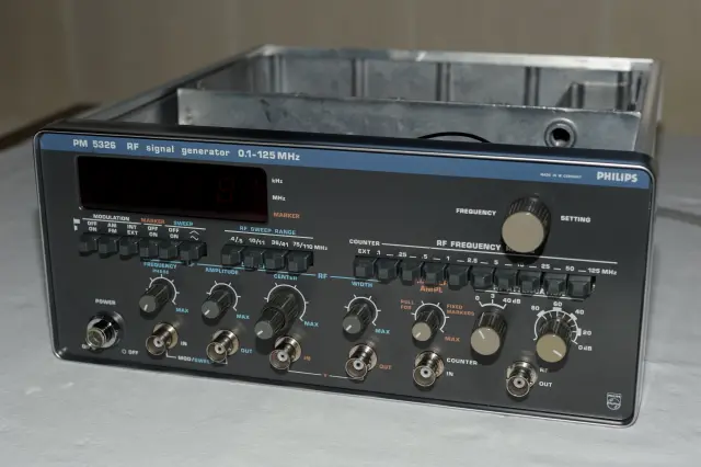
This is a mod using a DDS module to repair a drifty Philips PM 5326 RF generator. Stefan has done a marvellous job, not only of the mod, but also in providing the write-up and pictures presented below. Please see notes at the bottom re software and using the Simple DDS VFO project for this mod.
Philips PM 5326 RF generator DDS mod
Starting point for this project was a constant frequency drift of my Philips PM 5326 RF generator. Even after hours of warming up it doesn't come to a full stop. Furthermore tuning to a specific frequency was a touchy thing because no fine tuning was possible with the build in tuning capacitor. The RF section of the generator is based on the PLL principle. The reference frequency is generated by a VFO, comprising a simple transistor LC oscillator. This reference frequency determines the frequency of a VCO as the active element of the generator. It generates the RF frequency between 100 KHz and 125 MHz via several range coils and divider chains for the phase comparator. Every slight deviation in frequency of the VFO results in a relatively higher deviation of the VCO and therefore of the RF frequency. So, the weak point was the VFO, which was state of the art in the late 70's, early 80's. It was as good as was possible in those days. So, I decided to replace the "analog" VFO with a modern DDS-VFO. An additional requirement was, that the generator shoud remain in its original state. I never wanted to drill any holes to the case for adding any switches etc. The modification should not be seen from outside and it should be reversible. Browsing through the internet I found the "Simple DDS VFO" from Terry (VK5TM) which fits all my needs, except for the step size switch. But Terry thankfully updated the software for the microcontroller, so that the step size could be toggled with a push switch on a suitable encoder. The following pictures show how the project was realised:
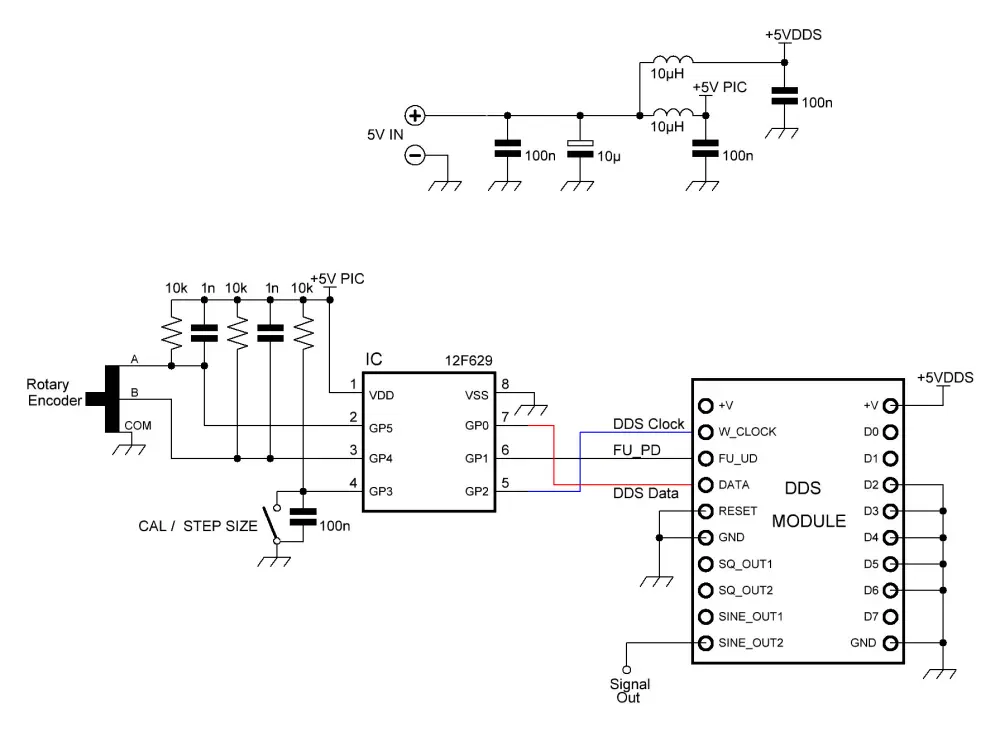
Pic_00: The circuit diagram, modified for my project. Power supply was altered and 100n cap fitted across the step switch.
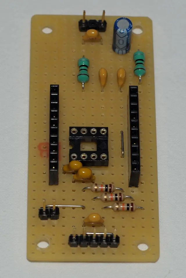
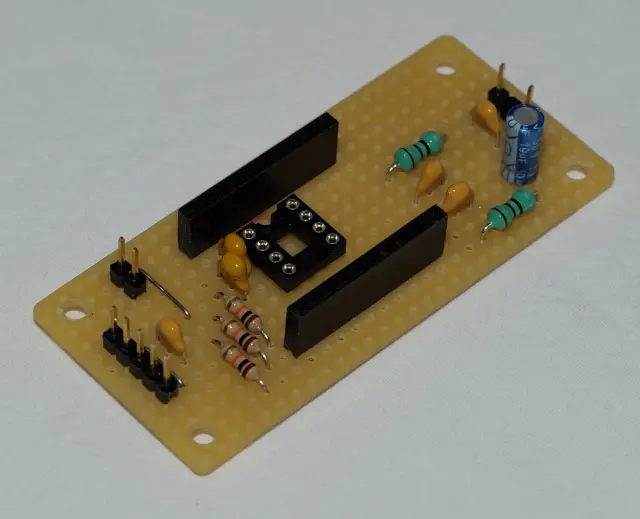
 Pic_01 + Pic_02: The DDS-VFO circuit build on a Veroboard.
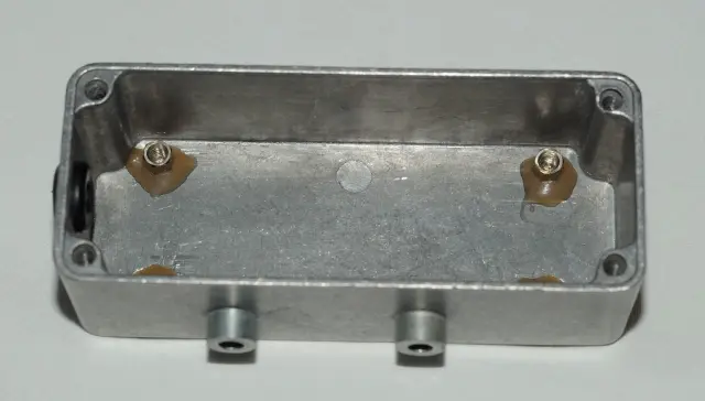
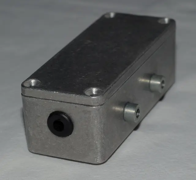
 Pic_03 + Pic_04: Aluminium die-cast case, ready to mount.
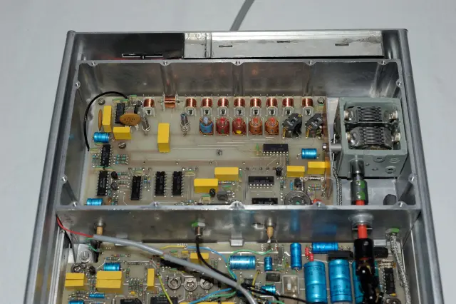
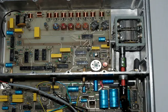
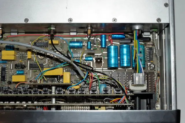
 Pic_05 + Pic_06: A look into the Philips PM5326 RF Generator.
You can see the RF-section opened with the VCO (0,1-125 MHz) and the VFO (498-1255 KHz) parts.
On the right side the tuning capacitor for the VFO. It has to be removed.
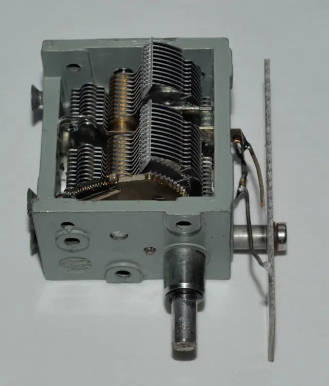
 Pic_07: The tuning capacitor removed. A lot of work to do that. The side panel has to be removed as well as the front plate of the generator.
 Pic_08: The empty space where the case for the DDS-VFO will be installed.
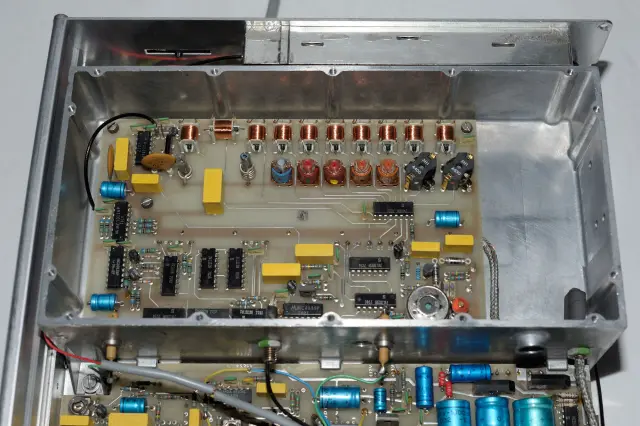 Pic_09 - Pic_11: The rotary encoder all ready in place with a new bracket.
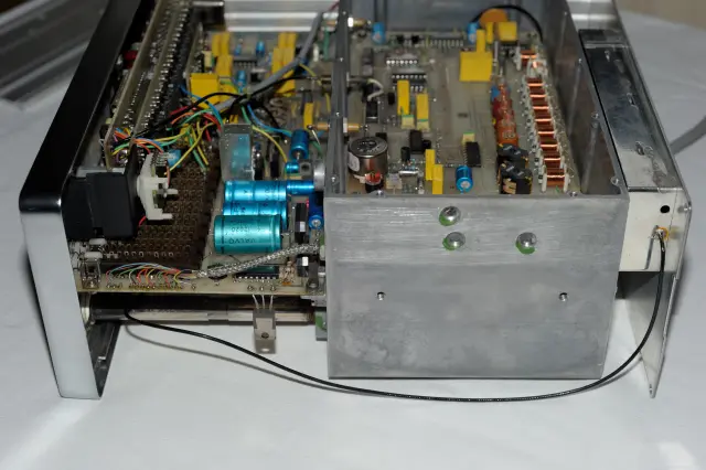
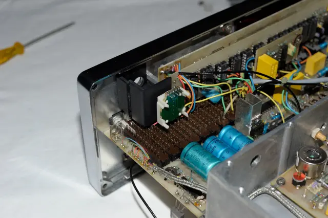
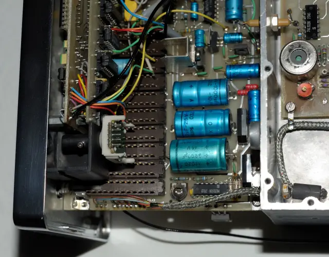 Pic_12 + Pic_13: The generator's front and side panel taken apart.
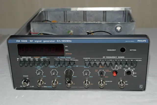
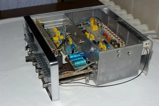 Pic_14 + Pic_15: The new die-cast case in place and the side panel mounted.
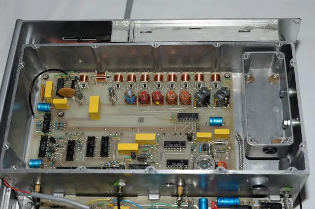
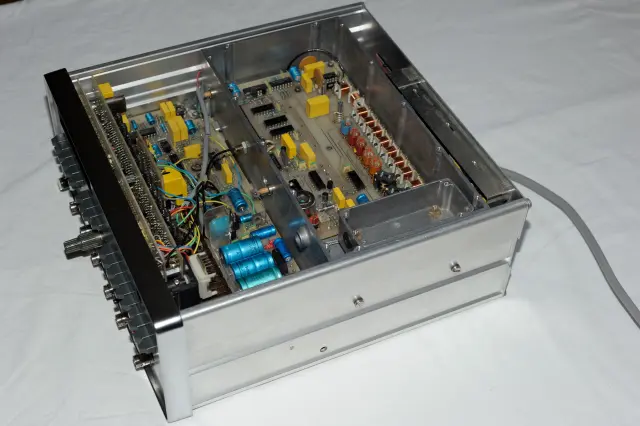 Pic_16: All the knobs fitted on the front plate.
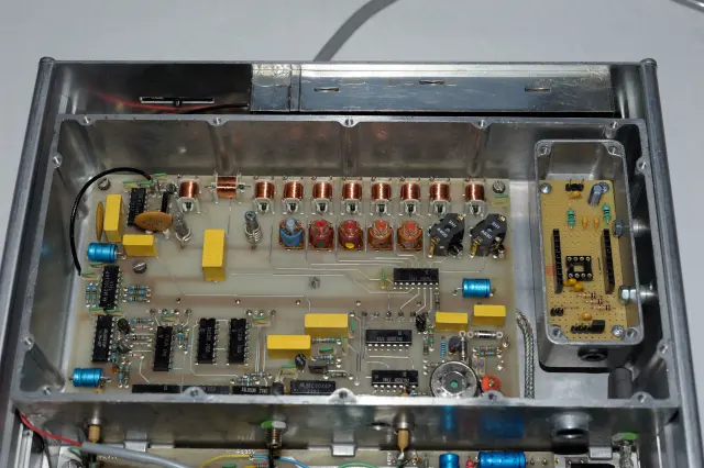
 Pic_17: The circuit built into the aluminium case.
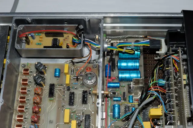
 Pic_18 + Pic_19 : The microcontroller 12F629 and the new wiring harness installed.

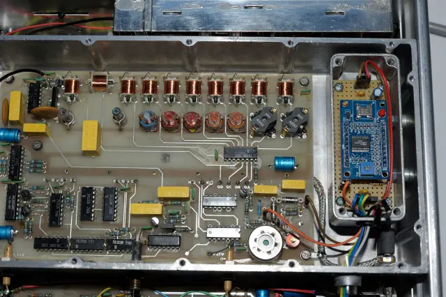
 Pic_20: Finally the AD9850 DDS-module on top of the veroboard.
 Pic_21 + Pic_22: Alignment of the DDS-VFO to the center frequency 876 KHz with my Racal Dana 1991 frequency counter (with OCXO option).
Frequency is spot on after 30 min. warm up time).
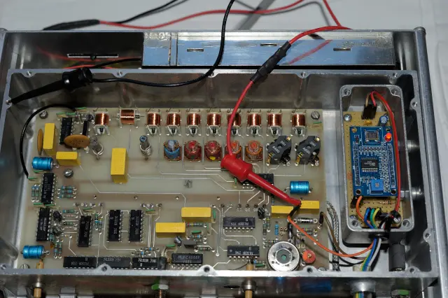
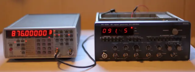 Pic_23: Fit the cover and tighten the screws of the DDS-VFO case.
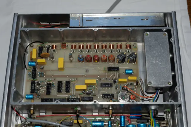 Pic_24: The same for the RF section of the generator.
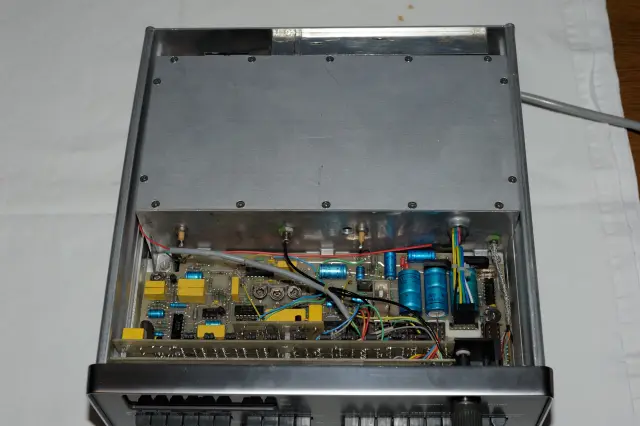 Pic_25: Wire harness of the encoder instead of the tuning capacitor's shaft.
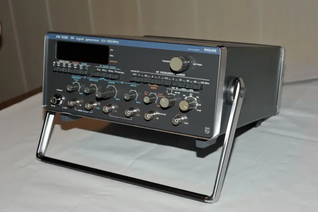
 Pic_26: The generator completely assembled and in its case. No optical changes visible. But the frequency setting knob now has a push button (built within the encoder).
 Pic_27 + Pic_28: The generator turned on and tuned to the FM and AM IF frequencies 10,7 MHz and 455 KHz repectively.
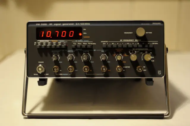
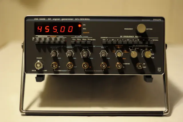
Frequencies now are absolutely stable and precise (tolerances of only a few hertz). A huge improvement to the former state ! The modification was worth all the efforts. I am very grateful to Terry for all his support and help making this project a great success.
Notes
Normally I have been emailing the PIC software for this mod to those requesting it. However, despite the schematic at the top of this page, some confusion has ensued when I mention you can use the Simple VFO pcb to build this mod. This confusion arises because the software was written for the older Simple VFO project and uses different connections for the encoder and switch. I have updated the software so that it is now directly compatible with the updated Simple DDS VFO project schematic and pcb, i.e. - you follow the Simple DDS VFO 2017 update project details and use the software posted at the bottom of that page for the PM5326 mod. Also, the pcb may be slightly too wide depending on how you fit it, so you may need to shave a couple of mm off two of the opposite sides or build it on a piece of strip board as in Stefans build above.
