News, Updates and Other Minutiae
August 2025 UR5WHK has created another version of the AD9833 project with a 128 X 32 OLED display. You can find it under the Gallery menu - it is on the same page as the MAX7219 version.
July 2025 UR5WHK has created an updated version of the AD9833 project which now includes a MAX7219 based LED display. Code updated 10 July 2025. Code updated again 15 July 2025. You can find it under the Gallery menu.
March 2025 In something of a "Seniors Moment", I forgot to update the homebrew menu and this section relating to a project I did late 2024. That project is an update of one from the RSGB Radcom magazine of Sept 1999 - 'Turn Your Dip Meter into a Signal Generator'. Presented here as 'Grid Dip Meter (GDO) Add on' under the Homebrew menu.
November 2024 Phillipe F6ETI has done some serious testing on the Noise Canceller and shown it works up to 72MHz and is usable with some loss at 145MHz. Links to his website with photo's, video's and description of the testing on the Noise Canceller page.
Privacy Policy uploaded. GPDR and all that stuff In accordance with various bits of legislation around the world, either currently in force, about to come into force or proposed, you will now find that annoying "We use cookies" notice at the top of this website. The full Privacy Policy is available at the Privacy Policy link in the footer at the bottom of the page. (If you don't know what GPDR is, Google it. Real scary shit for ANYBODY with a web presence.)
Order pcb's for this project here PCBway pcb order. At the Checkout, make sure to scroll down the page and select your preferred shipping option otherwise the most expensive option is automatically selected.
The pcb link above is the 2017 Simple DDS VFO pcb that can also be used for this project. You will just need to be a little inventive in mounting and wiring the AD9833 module. 16 Jan 2023 - added 12F1840 version of code. July 2025 See an updated version by UR5WHK which includes a LED display of the frequency. August 2025 UR5WHK version with OLED display added UR5WHK AD9833 VFO The project on this page has been updated to include the MAX7219 8 Digit 7segment display module - see further down the page.
AD9833 DDS VFO
A Simple AD9833 DDS based VFO using an 8-pin PIC.
Like my AD9850/51 based Simple DDS VFO, this is a VFO that can be used just as an ordinary transistor/fet VFO would be. This has been kept as simple as, any buffering, amplification or filtering is left up to you to build to suit your purposes. Why another DDS VFO and why the AD9833? Well, the AD9850/51 modules have become expensive and I've had a few requests over the last couple of years for a limited range device to use as a VFO, so I looked around and currently, the AD9833 modules (without all the extra's) are relatively cheap - around $6 AUD at the end of November 2022 - just watch the postage charge! Plus the other favourite, the Si5351 is in very short supply at the moment. First to note - this is a preliminary presentation of the project. The software is based on V2.4 of the 2017 Simple DDS VFO and features all the same functions but I have not fully tested that everything works as it should (mainly due to the current lack of a workshop), so if you find a bug, please let me know so I can correct it. Also note that the maximum frequency available can be set to 12MHz but I probably wouldn't top much more than 10MHz. This currently uses a 12F629 PIC, but I will update it to the 12F1840 in a little while.
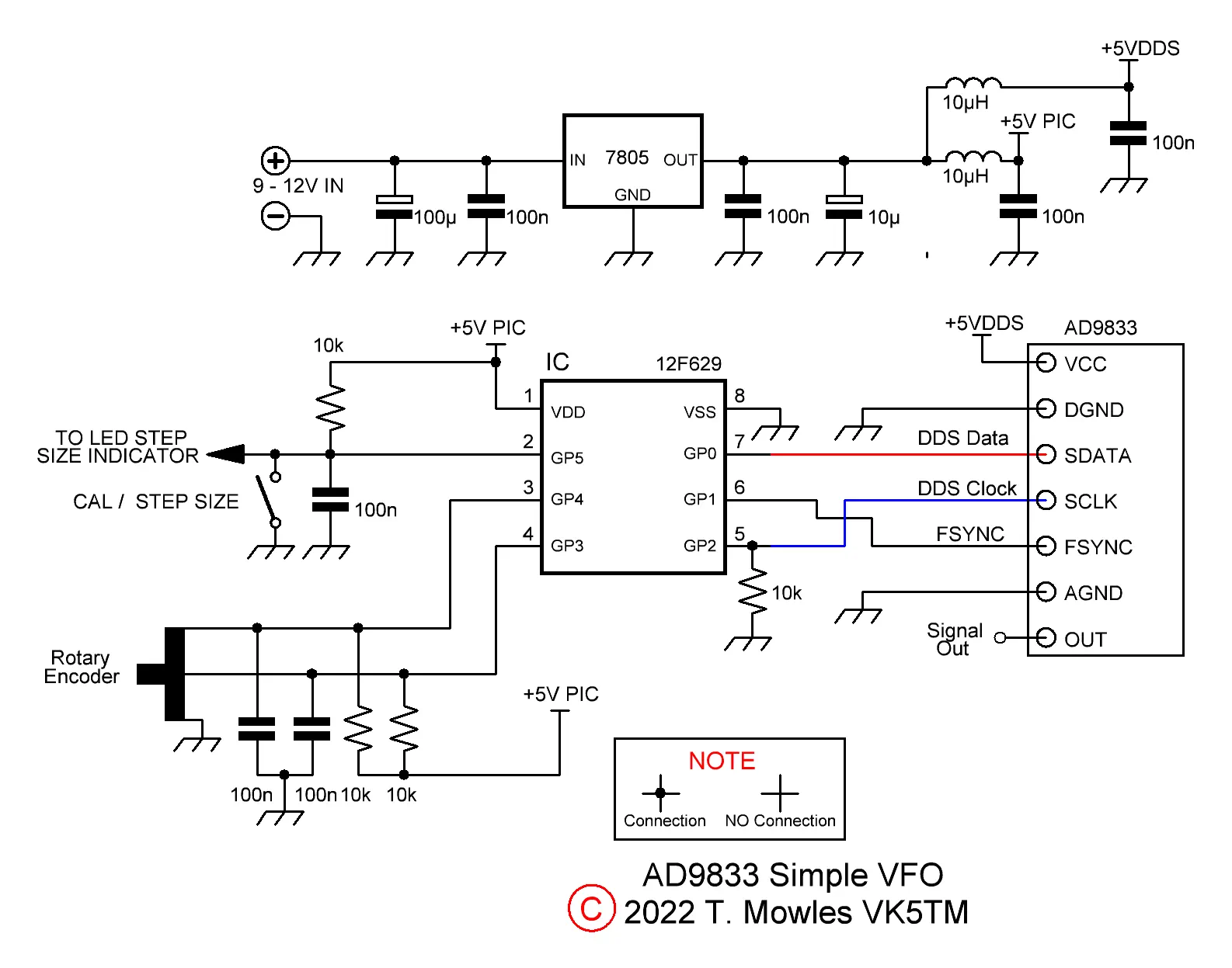
Note the resistor from pin 5 of the PIC to GND
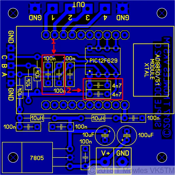
A note about the two sets of capacitors marked '1' & '2' in the original Simple DDS VFO project if you are using that pcb for this project - ignore the set marked a "2", ie the 4n7 ones - just fit the 100n ones in position "1"
Software
There have been a few cases of errors compiling files and it is caused by using an older version of MPlab. I use version 8.92 (which is the last of the old MPlab versions) and the problem relates to the 'include' file and the Config defines of those older versions. Specifically the FOSC_INTRCIO definition of the later version - change it to INTRC_OSC_NOCLKOUT for earlier versions of MPlab. A few words about the software. You will need to input the values of and recompile the software for your required VFO frequency: Limit - The upper limit frequency you want the VFO to reach. Limit_Low - The lower limit frequency you want the VFO to go down to. Default - The default start frequency - this will be overwritten during operation by your last used frequency, it is just the first time start up default (it must be within the VFO range above). Cal_freq - The Calibration frequency - This is the frequency the unit needs to be adjusted to during the calibration procedure. I suggest making it in the middle of your VFO range. In the file available to download below, the frequencies are 5.5MHz, 5.0MHz, 5.0MHz & 5.250MHz in order as listed above. There is no limit to the frequency range of the VFO other than that of the AD9833, so your limits could be 1Hz and 12MHz if that is what you wanted. At the first power-up, the step size is set to 10Hz and each subsequent push of the step switch advances the step size by 1 i.e. - to 1kHz and then 10kHz. Another push of the button steps back to the 10Hz step size. The step size set at power down will be restored the next time you turn the unit on. One point to note: Until the calibration is done, you need to make sure that the 'CAL/STEP' input is not held low when first turned on. Otherwise the unit will enter 'calibration' mode. Once the calibration has been done, this restriction does not apply. If you do not want to do a calibration, all you need to do is switch the AD9833 VFO into CAL mode and back out again without making any changes (see below). The software 'should' work with either mechanical or optical encoders. You need to remove the pullup resistors and associated caps on the encoder input lines to use an optical encoder (I have come across a couple of encoders that need the pull-up resistors left in place - check the datasheet of your particular encoder). You may notice at some point, regardless of encoder style used, that it appears to hesitate or not step the frequency. This is caused by the frequency save routine going off and doing it's thing. It is not a bug or fault, PIC's can only do one thing at a time, so it can't respond to the encoder while doing a frequency save. In the code below, the save delay is set to 2 seconds, increasing this to say 5 or 10 seconds may be beneficial.
Calibration
Once you have built the unit, it really should be calibrated before you fit it into anything. Calibration requires the use of an accurate frequency counter with 1Hz resolution and is used to adjust the "OSC" values in software to correct for off frequency Xtals on the DDS modules. Connect the frequency counter to the output of the unit and short the pads marked "CAL". The short must not be removed until calibration is complete. I would suggest you wire an on/off switch across the pads. With the pads shorted (or the switch "ON"), apply power. The frequency counter should show a frequency somewhere in the vicinity of the calibration value put into the software. Let the unit to run for a minimum of fifteen minutes before doing any adjustments and keep it out of any drafts. Turn the encoder in which ever direction is required to change the frequency so that it becomes your calibration value. Note that the oscillator calibration steps are very small, so you may have to turn the encoder a fair number of turns to reach your calibration frequency. Without turning the encoder further, remove the short (or turn the switch connected to the CAL input OFF) and then turn the encoder again (direction does not matter). This will save the new computed "OSC" values into EEPROM and the unit will now be functional. At this point, you can remove power and fit it into what ever it is you are going to use it in.
Calibration flag reset modification
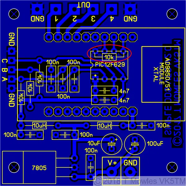
This info is on the 2017 Simple DDS VFO project page, but I will repeat it here:- In older versions of the software for the older Simple DDS VFO project, it was necessary to re-program the PIC if you wanted to do another calibration. This newer software does need a minor pcb mod though and the AD9833 module needs to be socketed so it can be removed for part of the procedure. Firstly the pcb mod - you need to fit a 10k resistor between pins 8 & 5 of the PIC, see below. It can easily be done under the pcb.
Next, you will need to make up a little wire jumper lead to connect between the two points shown below in orange (this not a permanent jumper, it is only used during the reset procedure).
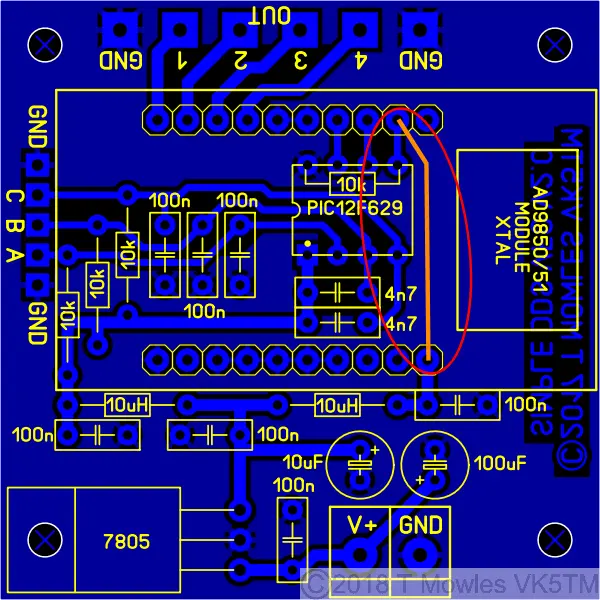
Program your PIC with the software in the downloads section. OK, now on to doing the reset procedure:- 1: With everything powered off, remove the DDS module. 2: Fit the temporary jumper as in the pic above. 3: Power up, leave for a couple of seconds and power down. 4: Remove the temporary jumper, refit the DDS module and carry on as per normal. You can now do another calibration run - no re-programming required. Each time you want to do another calibration, all you need to do is repeat the above procedure. Further information on modifying the software can be had from the 2017 Simple DDS VFO project as it is basically the same software although the line numbers mentioned on that page will be different. The "Step LED" add-on is also catered for in this project.
Downloads
These files are provided free for personal use ONLY. I retain copyright on all works published on this website (unless otherwise specified). These files, or any derivative of them, may NOT be used in any commercial or profit making enterprise of any kind. Updated August 2025 - new AD9833 initialisation procedure and remove some unnecessary calls.
(Right click and 'Save as..' or what ever is required by your browser) AD9833_VFO_V0-5b.asm The ASM file for the VFO. Default VFO range 5 - 5.5MHz. AD9833_VFO_V0-5b.hex AD9833 VFO hex file. Below are the 12F1840 files. There have been some changes - the rotary encoder routine has been changed and there is a major change to the upper and lower frequency limits checking routine. As before, these files have not been comprehensively checked for errors, so if you find any, please let me know so I can correct them. AD9833_VFO_V0-6b.asm The ASM file for the VFO. Default VFO range 5 - 5.5MHz. AD9833_VFO_V0-6b.hex AD9833 VFO hex file.
AD9833 + MAX7129 Display VFO
An update of the above project to include a MAX7219 8 Digit 7 Segment display module.
Firstly, a great deal of thanks is owed to Vasyl, UR5WHK, because, without his input, this update probably wouldn't have happened for quite some time (it was on the list of 'THINGS TO DO' with an OLED display). As per the title, the above project has now been updated to include a MAX7219 8 Digit 7 Segment display module and all still on an 8 pin PIC. First up, lets have a squizz at the schematic and the first thing you will notice is a lack of capacitors and resistors around the PIC. This is because the internal pull-ups of the PIC have been used to replace the external resistors and the capacitors used to debounce the encoder and switch have been replaced by software. Also, I have now run out of 12F629's and am using the 12F1840 as my goto 8 pin PIC.
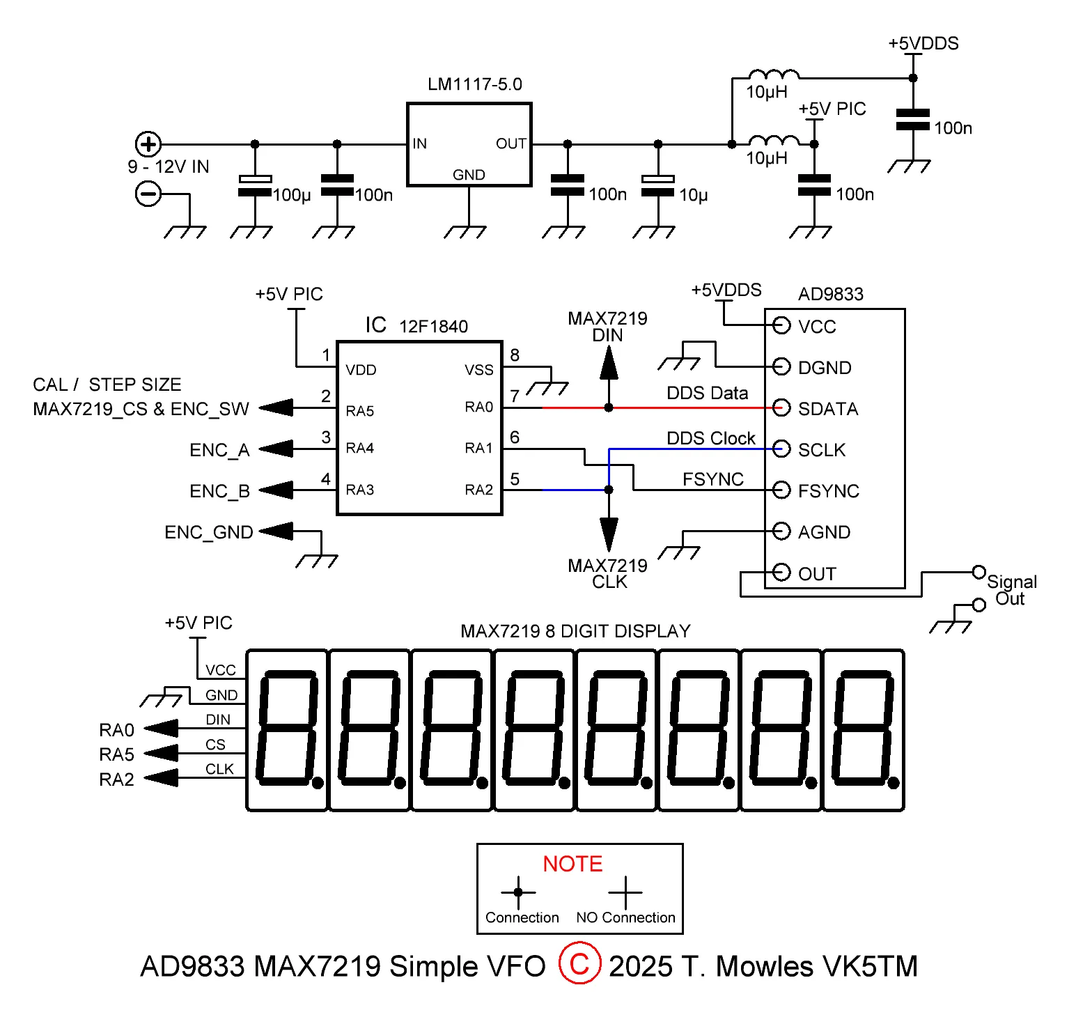
Note the resistor from pin 5 of the PIC to GND is no longer needed.
What else is different (besides the display)? Hardware wise, nothing really, although I've swapped to the low dropout LM1117 range of voltage regulators now. The standalone STEP LED indicator circuit is also not needed. To expand on the last comment, the Step size is now indicated using the very leftmost digit on the display - the bottom horizontal segment is lit on 10Hz steps, the bottom and middle ones are lit for the 1kHz steps and all three horizontal segments are lit for 10kHz steps. Also to note is that the 1Hz digit is not shown on the display. On to the software and all of the comments in the above Software paragraph are relevant (other than the beginning bit in red), so there's no need to repeat that here. For those that like to tie their brains up in knots, a large proportion of the software has been totally rewritten and is heavily based on Vasyl's code. The encoder and step switch functions are now looked after by an interrupt routine and switch/encoder debouncing is all handled by software. Functionally, nothing has changed - you turn a knob and the frequency either goes up or down, you push a button and the size of the step changes and 2 seconds after the knob stops turning, the current frequency and step size are saved to EEPROM. Calibration The comment about doing the calibration once assembled is still relevant and not pushing the encoder switch at power on (for normal operation) applies (the calibration lockout has been removed). What has changed is there is no need to perform a "reset" to do another calibration. To enter calibration mode, push the encoder switch and then power on the unit, let the switch go (after ~ 1 second) and you should see "CAL" displayed for 1 second and then the calibration frequency will be shown. Once the calibration has been performed as above, push and release the encoder switch again and the new calibration factor will be stored in EEPROM, then after another 1 second, the PIC will perform a reset and restart - there is no need to power down and back up again. Note that the displayed cailbration frequency does not change when the encoder is turned.
Downloads
These files are provided free for personal use ONLY. I retain copyright on all works published on this website (unless otherwise specified). These files, or any derivative of them, may NOT be used in any commercial or profit making enterprise of any kind.
(Right click and 'Save as..' or what ever is required by your browser) F1840_AD9833_VFO_MAX7219_V0-6.asm The ASM file for the VFO. Default VFO range 5 - 5.5MHz. F1840_AD9833_VFO_MAX7219_V0-6.hex AD9833 VFO hex file.
