News, Updates and Other Minutiae
August 2025 UR5WHK has created another version of the AD9833 project with a 128 X 32 OLED display. You can find it under the Gallery menu - it is on the same page as the MAX7219 version.
July 2025 UR5WHK has created an updated version of the AD9833 project which now includes a MAX7219 based LED display. Code updated 10 July 2025. Code updated again 15 July 2025. You can find it under the Gallery menu.
March 2025 In something of a "Seniors Moment", I forgot to update the homebrew menu and this section relating to a project I did late 2024. That project is an update of one from the RSGB Radcom magazine of Sept 1999 - 'Turn Your Dip Meter into a Signal Generator'. Presented here as 'Grid Dip Meter (GDO) Add on' under the Homebrew menu.
November 2024 Phillipe F6ETI has done some serious testing on the Noise Canceller and shown it works up to 72MHz and is usable with some loss at 145MHz. Links to his website with photo's, video's and description of the testing on the Noise Canceller page.
Privacy Policy uploaded. GPDR and all that stuff In accordance with various bits of legislation around the world, either currently in force, about to come into force or proposed, you will now find that annoying "We use cookies" notice at the top of this website. The full Privacy Policy is available at the Privacy Policy link in the footer at the bottom of the page. (If you don't know what GPDR is, Google it. Real scary shit for ANYBODY with a web presence.)
Modifying the Si5351 Local Oscillator Module frequency
January 2019 - I have just been alerted to the updated Clockbuilder software and it is completely different to the pictures on this page. I will do an update with new diagrams as soon as I can get to it.
Modifying the frequency of the Local Oscillator module is a relatively easy task, however, you will need PIC programming skills. To start, you will need the Clockbuilder software for the Si5351. At the time of writing this page, it is available here: http://www.silabs.com/products/clocksoscillators/pages/timing-software-development-tools.aspx Look for"Si5351" in the list. Once you have downloaded and installed it, start the software and you should see the following (without the red ellipses):
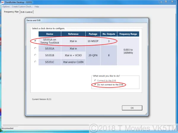
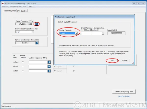
Select the options shown circled in red and click OK. This will take you to the main page. Click the arrow next to "Crystal Frequency" which will pop up the box where you select "25MHz" from the drop down list. Note that there are only two options, 27 or 25MHz. Again, click OK.
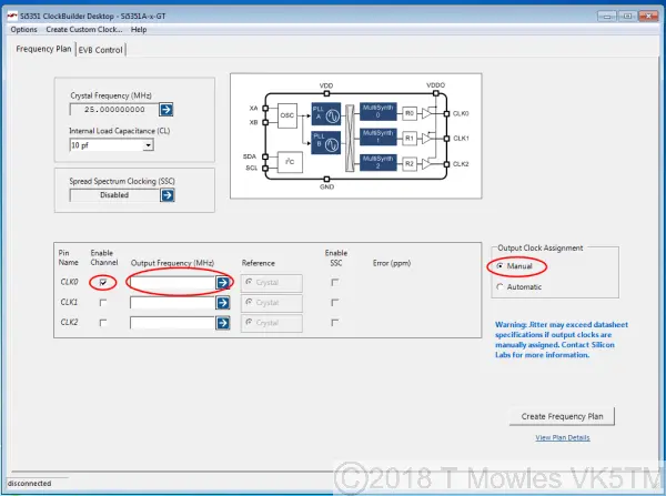
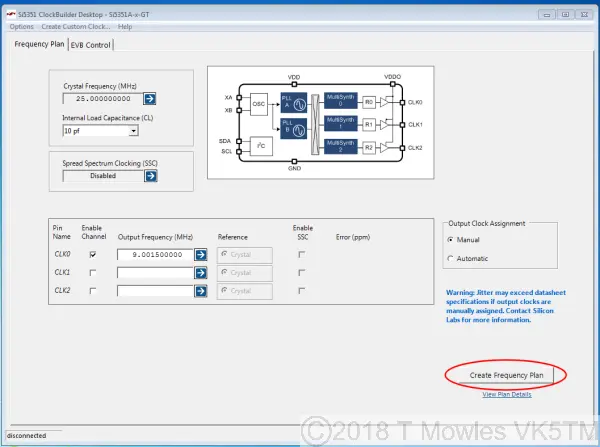
On this next page, click "Manual" first and then select the checkbox next to "CLK0". Ignore the warning that comes up, you are only using one output so there can be no jitter problems.
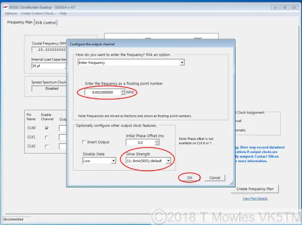
Clicking the arrow next to the blank "Output Frequency (MHz)" box will pop up a box where you can enter the frequency required and the "Drive Strength". You can select a drive strength of 2,4,6 or 8mA. Depending on your application, you will need to experiment with this setting. The higher the current level, the higher the output. For Pic-a-Star use, set this to 8mA. For this short article, I have entered an example frequency of 9.0015MHz for use as the LSB frequency with a 9MHz filter.
Once you have made your choices, click on the "Create Frequency Plan" button. Nothing will appear to happen, but it does generate the needed file. You can click the "View Plan Details link if you wish, but it will not tell you anything really useful.
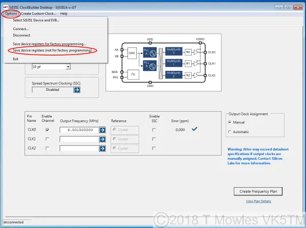
Now, and this is the important bit, click on "Options" in the top menu bar and select "Save device registers (not for factory programming)". This will bring up the normal Windows Save menu. Give the file a name and select a location to save it.
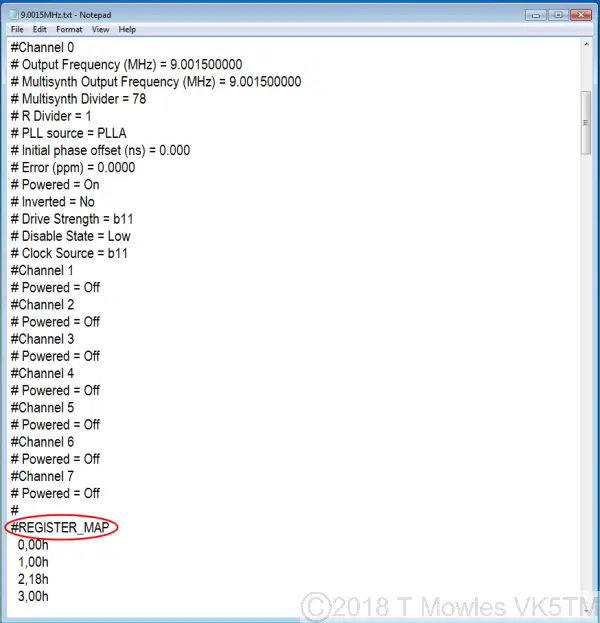
Once you have done that, you can now open the generated text file, the picture below is a portion of that file. The important bit is from the circled "Register_MAP" tag and below. What you need to do with information is explained in the following steps.
If you only want the one frequency, then you are finished with this step, if you want the choice of two frequencies that the LO module is capable of, then you need to do it all again and generate another file. Remember to save the second file with a different name.
Changing the PIC program
This will require reasonable PIC programming skills. I have commented the ASM file as much as possible, but if something is unclear, email me and I will clarify it as best I can and add additional info to this page if needed.
Firstly, a brief explanation of the text file that is generated by Clockbuilder. Everything with a "#" in front of it is a comment. At the top is information on the options selected when generating the file. Then you get to the important bit, the "Register_MAP". Parts of this are what is needed to be programmed into the PIC. The first digits on a line are the register number in decimal, followed by the command in hex. While the list runs from 0 to 232, you do not need to add all of these. The general sequence of programming the registers is shown in the code snippet below. First you send the address of the chip. The address of the chip is 0x60 as per the datasheet and, just to be confusing, the program snippet below shows 0xC0. Just trust me that it is correct. If you really need to know why, study the I2C protocol and how the addressing works. HINT - 7bits and MSB (Most Significant Bit) first. Following the sending of the IC address, you send the register address you want to program, 3 in the snippet below and then the command, H'FF'. At the end, you send the stop command. This is for individual, seperated registers. (Click picture for larger view. Click again to close.)

Where the register addresses are sequential, this will get very tedious, so as per the I2C specs, you can send the chip address, the address of the first register in the list to program and then sequentially send a list of commands. The Si5351 automatically steps to the next register in turn as you send the commands. Once you have reached the end of list, then you send the stop command. The short code snippet below is part of the sequence that programs registers 24 to 92 and the stop command is called at the end (not shown). (Click picture for larger view. Click again to close.)
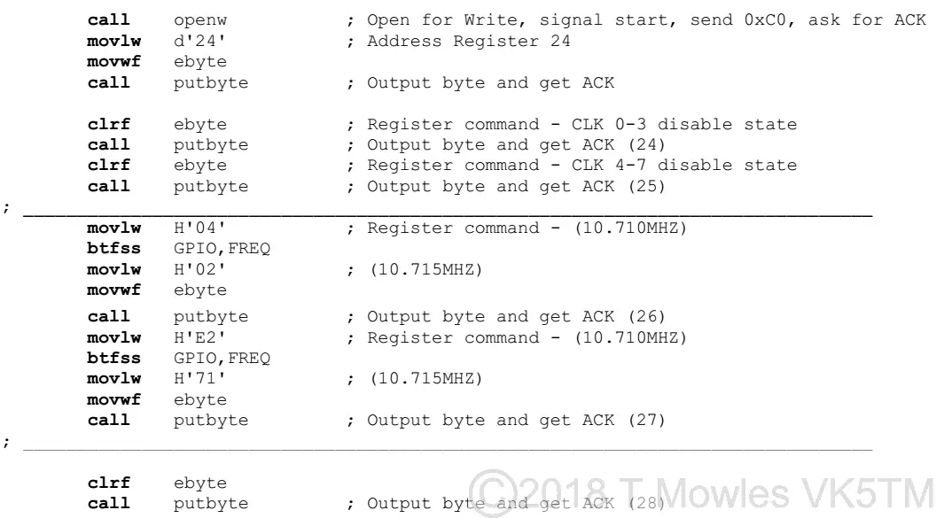
Now to the registers to be programmed, firstly for a single frequency. According to a post on the SiLabs forum it goes like this: 1. Disable all outputs. reg3 = 0xFF 2. Write reg187 = 0xC0 3. Power down all output drivers reg 16 = 0x80 reg 17 = 0x80 reg 18 = 0x80 reg 19 = 0x80 reg 20 = 0x80 reg 21 = 0x80 reg 22 = 0x80 reg 23 = 0x80 (Note that I haven't checked whether all 8 output registers are present in the 3-outout version of the Si5351, but it accepts the code, so they may be there.) 4. Set interrupt masks register (see Register 2 description in datasheet). I didn't do anything with this one. 5. If needed, set crystal load capacitance, XTAL_CL in reg183[7:6]. See datasheet for register description. 6. Write registers 15-92 and 149-170 using the contents of the register map generated by ClockBuilder Desktop. 7. Apply PLL A and PLL B soft reset. reg177 = 0xAC 8. Enable outputs with OEB control in register 3. (OEB = Output Enable Bits). So basically, you need to extract from the Clockbuilder file, all the values of registers 15 - 92 and 149 - 170 and transpose them into the appropriate places in the program. A lot of the values are 0x00, so in the asm file you will see the command "clrf ebyte", which is the same as loading it with a zero value. You may notice two or more consecutive sets of clrf ebyte, call putbyte and another clrf ebyte. This was done to make sure that the file remained at zero, as the STATUS C register is used in moving the bits out to the Si5351. Every line in the asm file corresponding to each register is marked with the register number as so (24). If you are doing a two frequency program, there is a preliminary step that needs to be done (note that, as the software currently stands, it will not switch between frequencies while powered up. I am working on another version of this software that can do so). You need to compare the two frequency plans and note which registers differ from each other. There will not be a large number of them. The code snippet below shows the structure of how the test is done to determine which frequency to generate. It first loads the default frequency value into the 'W' register of the PIC and then tests if the "FREQ" pin is low. If it is, it loads the new value into the 'W' register and proceeds to load that new value into the Si5351. You will find various sections delineated within the asm file where this happens with the current set of frequencies. (Click picture for larger view. Click again to close.)

NOTE -> SMOKE ALERT. If you have a fully loaded module with the PIC on board and are experimenting with changing the program, it is VITAL that your programmer does not output more than 3.3V on it's V+ pin. If it does, you will let out the all important smoke and the module will never work again.
Modifying the Si5351 Local Oscillator Module Part 2
I have pcb's available for sale at $5AUD each (+postage) and will supply a custom programmed PIC for $20AUD (+postage). My contact details are good on QRZ.com or via my contact page.
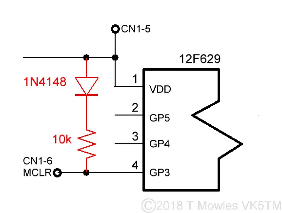
This is the second part of modifiying the SI5351 LO module such that it can switch between various frequencies and doesn't need to be powered down to do so. The only difference is a switch matrix using the "Frequency select" and one of the programming pins and modified software. As it stands, I have only used two pins for the frequency select function out of the four available, so this will give you the choice of 4 frequencies. The more ambitious among you may want to use all four available pins and get up to 16 frequencies. Note that internal pull-ups are used on the frequency select pins, but this function is not available on pin 4 of the 12F629 (GP3/MCLR), so you will need to add a pull-up resistor (10k) and an isolating diode to this pin. (Click picture for larger view. Click again to close.)
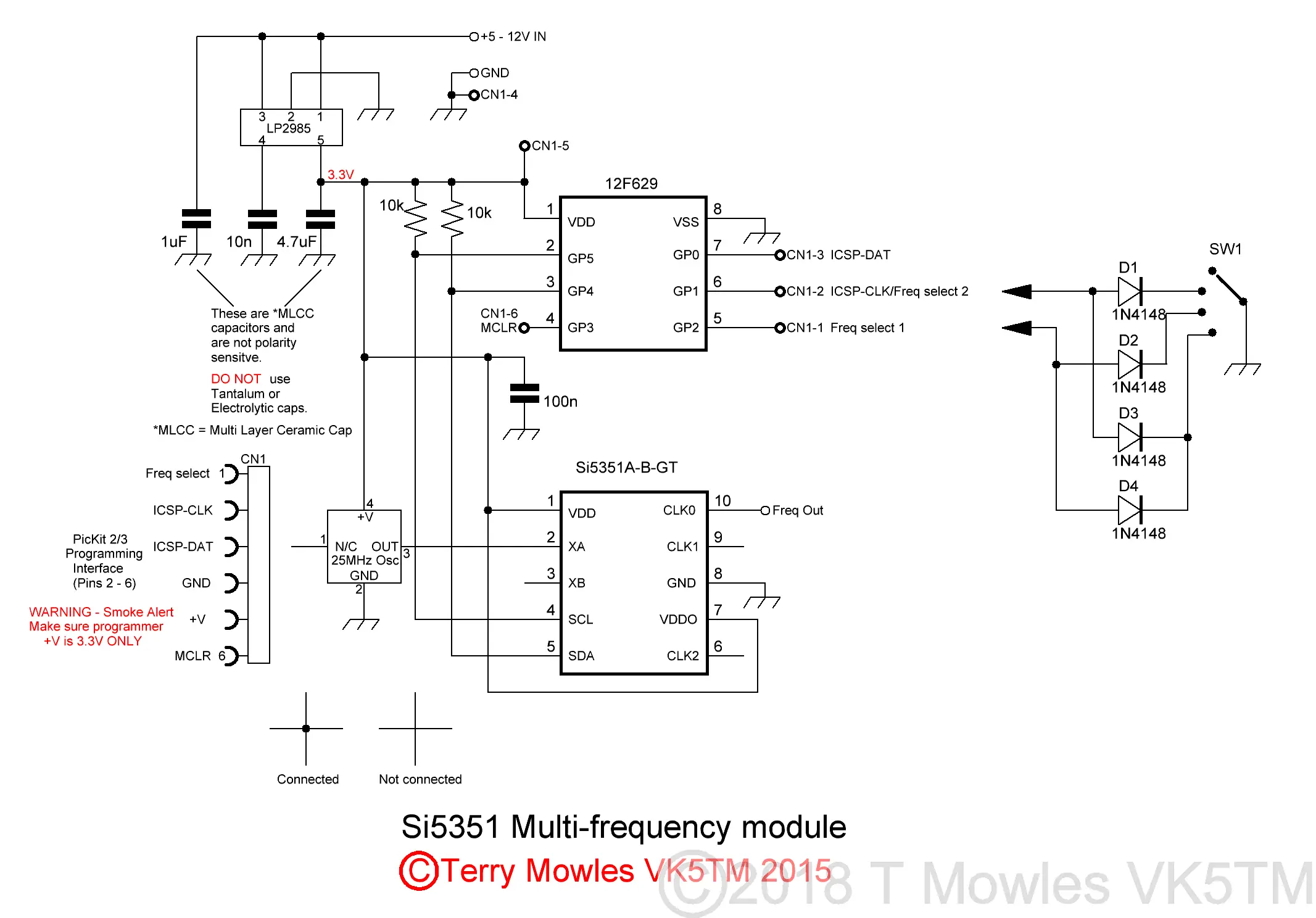
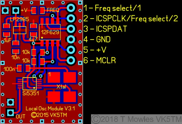
Below is the updated pcb that I have had made (apart from moving a couple of things, the pads for the xtal oscillator have been made bigger), showing the pins used for the frequency select function. I have not drawn a pcb for the diode switching, these can easily be mounted on the back of the frequency change switch.
Modifying the Si5351 Local Oscillator Module Part 2 Software
Below is an asm file, written at the request of another ham, that can be used as an example of how to accomplish multiple, live frequency switching. It is much the same as the original software as far as programming the Si5351 is concerned, but has had major changes to accomodate this modification. It now uses interupts. The PIC still goes to sleep when not actively reprogramming the Si5351. In this example, the four frequencies generated are: 54MHz, 53.9985MHz, 53.0015MHz and 53.9993MHz. Hopefully, it is commented enough for you to work out what is going on, email me if you need clarification on anything regarding this software. VK5TM_Si5351_Multi_LO.asm
