News, Updates and Other Minutiae
August 2025 UR5WHK has created another version of the AD9833 project with a 128 X 32 OLED display. You can find it under the Gallery menu - it is on the same page as the MAX7219 version.
July 2025 UR5WHK has created an updated version of the AD9833 project which now includes a MAX7219 based LED display. Code updated 10 July 2025. Code updated again 15 July 2025. You can find it under the Gallery menu.
March 2025 In something of a "Seniors Moment", I forgot to update the homebrew menu and this section relating to a project I did late 2024. That project is an update of one from the RSGB Radcom magazine of Sept 1999 - 'Turn Your Dip Meter into a Signal Generator'. Presented here as 'Grid Dip Meter (GDO) Add on' under the Homebrew menu.
November 2024 Phillipe F6ETI has done some serious testing on the Noise Canceller and shown it works up to 72MHz and is usable with some loss at 145MHz. Links to his website with photo's, video's and description of the testing on the Noise Canceller page.
Privacy Policy uploaded. GPDR and all that stuff In accordance with various bits of legislation around the world, either currently in force, about to come into force or proposed, you will now find that annoying "We use cookies" notice at the top of this website. The full Privacy Policy is available at the Privacy Policy link in the footer at the bottom of the page. (If you don't know what GPDR is, Google it. Real scary shit for ANYBODY with a web presence.)
Frequency Dependant Switch
A PIC based switch that detects the input frequency and sets 1 of 8 outputs.
The genesis of this project is the Pic-a-Switch by Peter Rhodes G3XJP and first published in the RSGB magazine Radcom between September and December 2001. Please note that, for copyright reasons, I cannot provide either the original software or copies of the articles. This all started off when one of my regular contacts mentioned he was looking for something that would automatically select the correct filter for his new linear amp he is building, depending on frequency. Of course, he needed some functions and not others, so started the modification process. Along the (still proceeding) way, I thought a few other changes might be in order. The original G3XJP project had:- The ability to change various settings using CW indication and various jumpers. A combination of RF and PTT detection at the same time. A top end limitation on frequency of 30MHz (software, not hardware limited). Output band switching lines were spread across two different PIC ports. And the changes made so far:- The ability to change various settings has been removed (this unit is going to be set and forget once finished). PTT only detection. All band switching outputs now on the one port. Different RF input circuit. Software changes include the storage of variables as a table rather than in EEprom. An option for a 6m (50-54MHz) output is in the pipeline.

Notes on the schematic
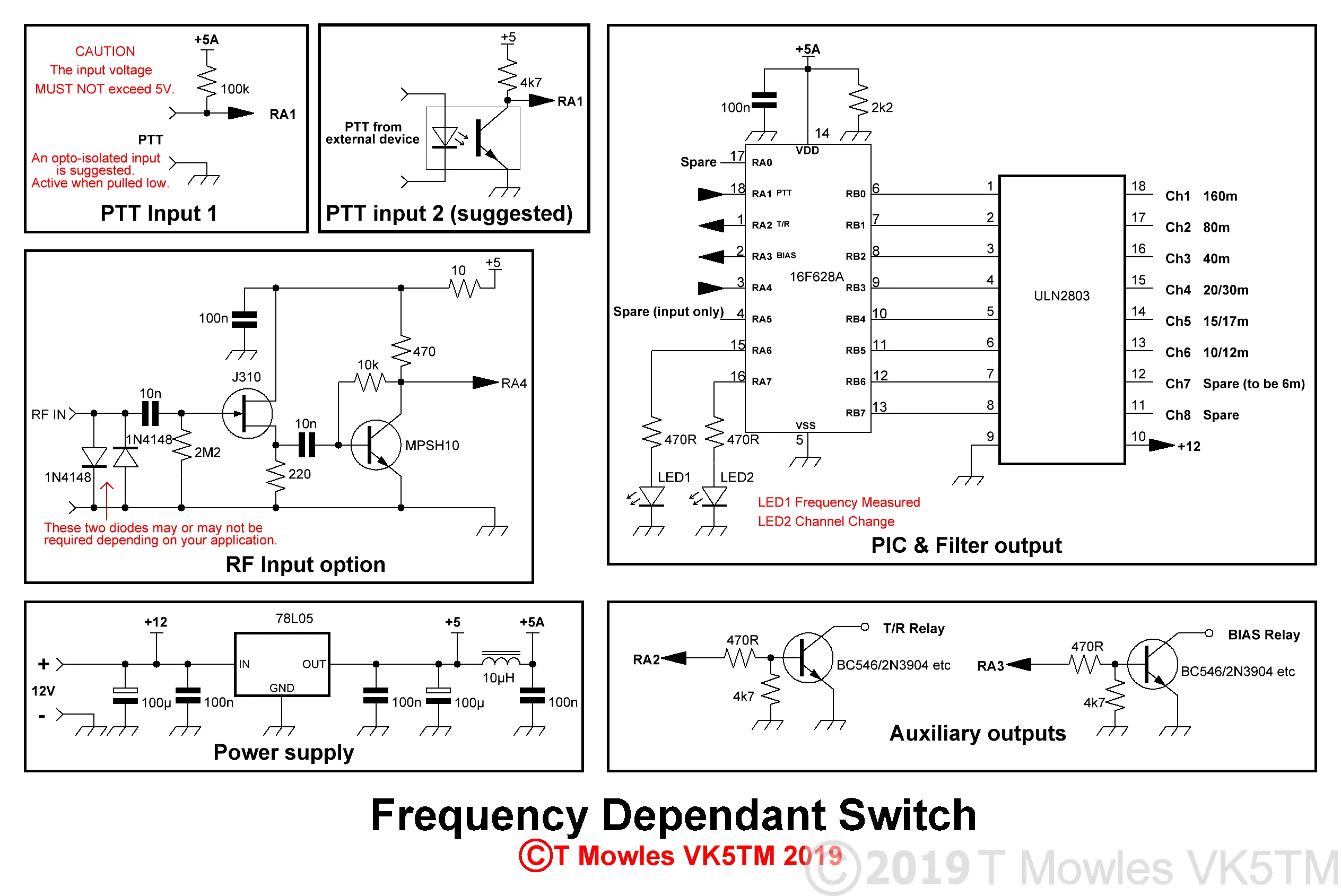
Firstly, the PTT input - this line is directly connected to the PIC, so, in your application I would strongly suggest adding some sort of opto-isolation between this circuit and whatever you are connecting it to. Any voltage on this line above 5V will let the magic smoke out and this stuff is getting hard as well as expensive to find. Not only that, it is impossible to stuff back in with any great success - you have been warned. The 100k resistor between pin 18 and the +5a rail can be adjusted to suit.
The 10k SIL resistor network between the PIC and the ULN2803 is probably not needed. Once the final circuit is assembled, this will be confirmed.
The 10k SIL referred to above is not required when using the ULN2803 (schematic above has been updated to reflect this). You can also use seperate transistors for the outputs, just duplicate the T/R relay output stage (but this seems a lot of work and components).
Although two of the outputs are labelled T/R Relay and BIAS, you can use them for what ever purpose is required. Also, the two LED outputs could be repurposed to other functions.
LED's 1 and 2 don't have to be installed, although I would suggest that LED1 at least be used. It will give an indication if something has gone wrong in the frequency measuring department such as no RF input or you've modified the software and something has gone awry.
There are also two other spare pins on the PIC (but one can only be used as an input), which, at the time of writing, there is no planned usage for.
Because I have been doing the testing/prototyping using a DDS module for the frequency input, a better input stage has proven to be required. The original input stage just wouldn't cut it with levels of 2-3mW in. You can use whatever input circuit will give you a healthy 5V p-p signal on pin 3 of the PIC, with the proviso not to exceed the 5V level.
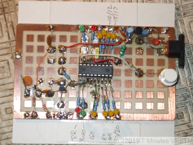
Just for laughs, this is the current state of the prototyping. There's no ULN2803 yet, with LED's indicating the state of the outputs, as I am mainly concentrating on the software at the moment (which for the most part is finished, but thorough testing is needed before I release it into the wild). V0.3 of the software below in the downloads section.

PCB
I have done the first draft of a pcb for this project, but until the project is finalised, I will leave the details for later. If there is enough interest, I will consider having pcb's made, but as per my other projects, the pcb files will not be posted. You can blame those without a conscience and illegally profiting from the work of others for this state of affairs.
Software
There are two versions of the software in the pipeline. One with PTT only activation and one with RF detection activation.
The PTT version has been posted below for download and I'm pretty certain it is bug free, but if you do find a problem, please let me know so I can tear out the last of my hair.
Well, famous last words, turns out there was a bug "feature" that meant that, while the software worked fine in any mode with a constant carrier, it wasn't happy with SSB mode. Ver 0.3 has now been posted to correct that "feature".
I do not know how well this project will work with any of the digital modes (WSPR, FT8 etc, etc), as I currently don't operate any of those modes. But if you do build this and try it with those modes, please let me know how you get on.
First version is the "PTT" version.
The sequence of operation (ignoring all the housekeeping and start up functions) is:
Set output to highest band (10m)
Wait for PTT to be activated
Once PTT activated, wait for RF to appear <-- "Bug" fix
Measure incoming RF, LED1 lights on a successful measurement (on error, go back to start)
Set output as defined by frequency - note that outputs have 'make before break' functionality when changing band.
Activate T/R relay after delay (adjustable in software)
Activate BIAS output after delay (also adjustable in software)
Wait for PTT to be released
Deactivate BIAS output
Deactivate T/R relay after delay (adjustable in software)
Go back to waiting for PTT
The band output remains activated when the PTT is released.
The asm file is well commented and basically follows the above sequence.
Adjusting the various delays is done by changing the values in this block of code near the top of the asm file (allowable values are 1 - 255):
; decimal #'s following equal time in mS (approx)
#define tA d'15' ; T/R relay operate delay time
#define tB d'15' ; bandsw relay operate time
#define tC d'8' ; bandsw relay release time
#define tD d'20' ; Bias operate delay
#define tE d'10' ; Debounce time
Because we are now using the internal oscillator of the PIC and it is only specified as having an accuracy of 1%, there is a possibility that the frequency measuring routine in software may need trimming (several 16F628A's I have trialled did not need trimming). The symptons of requiring trimming are that either the band switching may be slightly off with regard to actual frequency that it switches at or the T/R or BIAS outputs do not switch on. Note that the band limits are very generous because of the very simple frequency count routine used. To adjust the timing of the frequency measuring routine, all that is needed is to adjust the delay time as indicated in this code snippet below.
delay_150uS
;PIC Time Delay = 0.00014900 s with Osc = 4,000,000 Hz
movlw d'48' ; Adjust up or down if BIAS LED
movwf delay1 ; doesn't light on some channels
; or band switching is intermittent on some bands
loop
decfsz delay1,f
goto loop
return
6m Option
I have posted code with the 6m output option as a seperate file (below). There is a gotcha at this stage, I have not tested this properly in the test board, as the output of the DDS module is not brilliant and it gives the occasional error. I have tested it in the simulator and according to that, it is doing what it is supposed to (I will bring the proper signal generator in later and test with that, but the computer desk is getting somewhat crowded at the moment). Another point to note is that some 16F628A's work fine up to the 60MHz mark without problem, some don't. So do the tests before committing to use this version in any serious application. Also, without a lot of mucking about in the software and hardware, 6m is the highest band that this project will go. A note on the frequency count routine The frequency count routine is a very simple one devised by Peter. Basically, it counts the number of cycles over a 150uS period and the number in TMR0 is then used to set the filter output directly (the prescaler count is ignored). To work out what the expected count will be in TMR0, it is freq in MHz divided by 256 multiplied by 150 and then round to nearest integer. For example: 80m = 3.5 divided by 256, multiplied by 150 = 2.05078125, rounded to the nearest integer = 2. Note that only the most significant digits of the frequency are used, in this case 3.5. If you want to confirm what TMR0 is holding for a given frequency in a physical circuit, I have added a simple test program to display the TMR0 count (in binary) on LEDs connected to PortB below (LEDs are connected in series with a 470 ohm resistor between PortB outputs and ground).
Downloads
All files provided here are free for personal use ONLY. I retain copyright on all works published on this website (unless otherwise specified). These files, or any derivative of them, may NOT be used in any commercial or profit making enterprise of any kind nor for personal gain.
(Right click and 'Save as..' or what ever is required by your browser) VK5TM_FDS_PTTV0_3.asm The ASM file for the PTT version. VK5TM_FDS_PTTV0_3.HEX Hex file for above. VK5TM_FDS_PTT_50Mhz_V0_1.asm The ASM file for the PTT version with 6m output. VK5TM_FDS_PTT_50Mhz_V0_1.HEX Hex file for 6m option. TMR0 test program FDS_TMR0_count.asm FDS_TMR0_count.HEX
